
Rcl57 debug psu

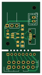
About the Rcl57 debug psu PCB
Rcl57 debug psu is an open source PCB design by tomcircuit, published on GitHub. It is a 2-layer board measuring 20 × 37.5 mm, with 11 components from 10 distinct parts.
Other key parts include the Microchip MCP73831T-2ACI/OT. By type, the board carries 5 connectors, 2 capacitors, 2 resistors, 1 IC and 1 diode.
It belongs with the retro computing designs in this gallery.
From the project
MCU-based retrofit to TI-57 Programmable Calculators
This project came about because I stumbled across a TI-57 calculator with a "bad brain". The TMC1501 calculator-on-a-chip was faulty. This, in turn, led me to read more about this particular calculator and how the CPU inside functions.
Fortunately, I am 'standing on the shoulders of giants' here - three people that have been of great help to me are Joerg Woerner, Jeff Parsons and Paul Novaes. All have humored me by answering my emails and helping me understand how the hardware works.
Main components on the Rcl57 debug psu
Rcl57 debug psu bill of materials (BOM)
11 components, 10 distinct parts — part numbers from the project's BOM.
| Qty | Part | Footprint | Refs |
|---|---|---|---|
| 1 | Microchip MCP73831T-2ACI/OT MCP73831-2-OT | SOT-23-5_HandSoldering | U101 |
| 1 | Molex 105017001 USB_Micro-B_Molex-105133-0001 | USB_Micro-B_Molex-105133-0001 | J101 |
| 1 | S2B-PH-K-S(LF)(SN) JST PH 2mm | JST_PH_B2B-PH-K_1x02_P2.00mm_Vertical | J102 |
| 1 | CALC | PinHeader_1x03_P2.54mm_Vertical | J103 |
| 1 | RCL57_BOARD | PinSocket_1x08_P2.00mm_Vertical | J201 |
| 1 | DEBUG | PinHeader_2x06_P2.54mm_Vertical | J202 |
| 1 | Wuerth 156120VS75300 LED | LED_0805_2012Metric_Pad1.15x1.40mm_HandSolder | D101 |
| 2 | MuRata GRM21BR71C475KE51L 4.7uF | C_0805_2012Metric | C101, C102 |
| 1 | 4.7K | R_0805_2012Metric_Pad1.20x1.40mm_HandSolder | R101 |
| 1 | 470 | R_0805_2012Metric_Pad1.20x1.40mm_HandSolder | R102 |
Rcl57 debug psu design files
The KiCad project lives in the tomcircuit/rcl57mcu repository on GitHub; these links point at the commit this page was built from.
Rcl57 debug psu: common questions
How big is the Rcl57 debug psu PCB?
The Rcl57 debug psu measures 20 × 37.5 mm, has 2 copper layers and is 1.6 mm thick.
How many components are on the Rcl57 debug psu?
11 components, from 10 distinct parts, with part numbers taken from the project's own BOM. The full bill of materials is listed on this page.
Where can I download the Rcl57 debug psu design files?
From the tomcircuit/rcl57mcu repository on GitHub, which has the KiCad layout, the schematic and the BOM; the links under Design files point to each one.
Can I use the Rcl57 debug psu design in my own project?
The repository has no license, so all rights stay with tomcircuit. Use it as a reference, and ask the author before reusing the design.
More boards in rcl57mcu
Similar boards
OpenTendo
Redherring32
196.3 × 118.7 mm93 parts2LTAPR-OHL-1.0850
MCL86jr
MicroCoreLabs
56.1 × 57.1 mm66 parts4LNo license532
24pin flex interposer
Wren6991
29 × 32 mm3 parts2LNo license508
Sram dev board
50 × 50 mm12 parts2LNo license508
TRS-80 Color Computer 3
baldengineer
280 × 155.3 mm204 parts2LCC-BY-4.0442
Commodore Plus 4
284.7 × 158.9 mm212 parts2LCC-BY-4.0442