
LEDTimer

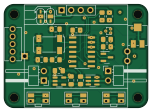
About the LEDTimer PCB
LEDTimer is an open source PIC PCB design by tomikaa87, published on GitHub under the GPL-3.0 license. It is a 4-layer board measuring 38 × 27.3 mm, with 28 components from 22 distinct parts.
Its main chip is the PIC16F18326, from the PIC family. Other key parts include the AP7383-36WW7, Display_128x64_096_I2C and BCR_421U_E6327. By type, the board carries 6 resistors, 4 ICs, 4 switches, 2 connectors, 2 jumpers and 2 capacitors.
It belongs with the displays & leds and power & battery designs in this gallery.
From the project
Programmable timer for low voltage LED lights (e.g. christmas LED strings) with a Microchip PIC16
This project is in work-in-progress state
A custom-made PCB and a 3D-printable enclosure is still in development and should be published soon.
I've made a simple 3D-printable case in FreeCAD. It's a two-part design which can be assembled using M2 self-tapping screws.
The first version of the PCB is a 4-layer design that can be manufactured for $2 at JLC PCB. It's almost as small as the 0.96" SSD1306 OLED display module itself. Because different display modules have varying pinouts (VDD and GND swapped), the function of the first two pins are configurable via solder jumpers (JP1 and JP2).…
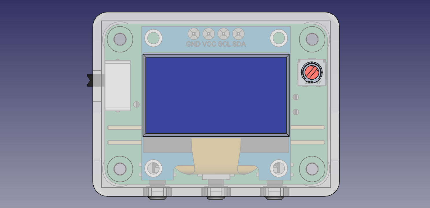
Main components on the LEDTimer
LEDTimer bill of materials (BOM)
28 components, 22 distinct parts.
| Qty | Part | Footprint | Refs |
|---|---|---|---|
| 1 | AP7383-36WW7 | SOT-23-5 | U1 |
| 1 | PIC16F18326 | SOIC-14_3.9x8.7mm_P1.27mm | U2 |
| 1 | Display_128x64_096_I2C | Display_128x64_096_I2C | U3 |
| 1 | BCR_421U_E6327 | SC-74-6_1.5x2.9mm_P0.95mm | U4 |
| 1 | S8050 | SOT-23 | Q1 |
| 1 | 32.768 kHz | Crystal_SMD_Abracon_ABS25-4Pin_8.0x3.8mm | Y1 |
| 1 | LED | PinHeader_1x02_P2.54mm_Horizontal | J2 |
| 1 | PWR | PinHeader_1x02_P2.54mm_Horizontal | J3 |
| 1 | HU2032-LF | Renata-HU2032-LF-0-0-0 | BT1 |
| 2 | 22p | C_0805_2012Metric_Pad1.18x1.45mm_HandSolder | CD1, CG1 |
| 1 | OLED_PIN1 | SolderJumper-3_P1.3mm_Open_RoundedPad1.0x1.5mm | JP1 |
| 1 | OLED_PIN2 | SolderJumper-3_P1.3mm_Open_RoundedPad1.0x1.5mm | JP2 |
| 1 | 220k | R_0805_2012Metric_Pad1.20x1.40mm_HandSolder | RD1 |
| 1 | R_Potentiometer | Potentiometer_Vishay_TS53YJ_Vertical | RVext1 |
| 3 | SW_Push | EVQ9P701P | SW1, SW2, SW3 |
| 1 | SW_PWR | 1825232-1 | SW4 |
| 1 | BAT54C | SOT-416 | D1 |
| 2 | 1u | C_0805_2012Metric_Pad1.18x1.45mm_HandSolder | C1, C2 |
| 1 | 47k | R_0805_2012Metric_Pad1.20x1.40mm_HandSolder | R1 |
| 1 | 100k | R_0805_2012Metric_Pad1.20x1.40mm_HandSolder | R2 |
Show 2 more
| Qty | Part | Footprint | Refs |
|---|---|---|---|
| 2 | 10k | R_0805_2012Metric_Pad1.20x1.40mm_HandSolder | R3, R5 |
| 2 | 4k7 | R_0805_2012Metric_Pad1.20x1.40mm_HandSolder | R4, R6 |
LEDTimer design files
The KiCad project lives in the tomikaa87/led-timer repository on GitHub; these links point at the commit this page was built from.
LEDTimer: common questions
What microcontroller does the LEDTimer use?
The LEDTimer is built around the PIC16F18326, from the PIC family.
How big is the LEDTimer PCB?
The LEDTimer measures 38 × 27.3 mm, has 4 copper layers and is 4.69 mm thick.
How many components are on the LEDTimer?
28 components, from 22 distinct parts. The full bill of materials is listed on this page.
Where can I download the LEDTimer design files?
From the tomikaa87/led-timer repository on GitHub, which has the KiCad layout and the schematic; the links under Design files point to each one.
Can I use the LEDTimer design in my own project?
Yes, under the terms of its GPL-3.0 license, which tomikaa87 chose for the repository.
Can I test firmware for the LEDTimer without the hardware?
Yes. HardLabs builds a simulation of the board from its netlist and BOM, so you can run and debug PIC firmware against it before you order a PCB.
More boards in led-timer
Similar boards
 PIC
PICPslab hardware
fossasia
99 × 53.3 mm187 parts4LApache-2.01.7k PIC
PICMicro 8088
skiselev
152.4 × 101.6 mm71 partsGPL-3.0414 PIC
PICGB-LIVE32
Gekkio
51.4 × 61 mm46 parts4LCC-BY-4.0376 PIC
PICGB-BENCH-G1
100 × 100 mm98 parts4LCC-BY-4.0376 PIC
PICGB-CARTPP-DIY
100 × 100 mm22 parts2LCC-BY-4.0376 PIC
PICGB-MBCTEST
51.4 × 61 mm32 parts2LCC-BY-4.0376