
Pocket sdr v2.3

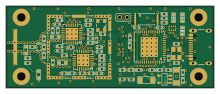
About the Pocket sdr v2.3 PCB
Pocket sdr v2.3 is an open source PCB design by tomojitakasu, published on GitHub under the BSD-3-Clause license. It is a 4-layer board measuring 55 × 21.6 mm, with 76 components from 34 distinct parts.
Other key parts include the MAX2771, CY7C68013A-56LTXCT, AT24C128C and LDO 3.3V 500mA SOT23-5. By type, the board carries 43 capacitors, 13 resistors, 5 ICs, 3 connectors, 3 LEDs and 3 inductors.
It belongs with the rf & radio designs in this gallery.
From the project
Pocket SDR FE 2CH is an open-source GNSS SDR RF frontend device for Pocket SDR. The device consists of 2 CH Maxim MAX2771 ([1]) GNSS RF front-end ICs (LNA, mixer, filter, ADC, frequency synthesizer) and a Cypress EZ-USB FX2LP USB 2.0 controller ([2]) to connect to host PCs. The f
Pocket SDR FE 2CH is an open-source GNSS SDR RF frontend device for Pocket SDR. The device consists of 2 CH Maxim MAX2771 ([1]) GNSS RF front-end ICs (LNA, mixer, filter, ADC, frequency synthesizer) and a Cypress EZ-USB FX2LP USB 2.0 controller ([2]) to connect to host PCs. The front-end CH1 is dedicated for GNSS L1 band (1525 - 1610 MHz), and CH2 is for GNSS L2/L5/L6 band (1160 - 1290 MHz). The frequency of the reference oscillator (TCXO) is 24.000 MHz, and the ADC sampling frequency can be configured up to 32 MHz.
Main components on the Pocket sdr v2.3
Pocket sdr v2.3 bill of materials (BOM)
76 components, 34 distinct parts.
| Qty | Part | Footprint | Refs |
|---|---|---|---|
| 2 | MAX2771 | TQFN28 | U1, U2 |
| 1 | CY7C68013A-56LTXCT | QFN56 | U3 |
| 1 | AT24C128C | TSSOP_8P | U4 |
| 1 | LDO 3.3V 500mA SOT23-5 | SOT23 | U5 |
| 1 | PINH_2MM_2P | PINH-2MM-2P | J1 |
| 1 | USB_C_Receptacle_USB2.0 | USB_C_Receptacle_GCT_USB4105-xx-A_16P_TopMnt_Horizontal | J2 |
| 1 | SMA-ANG | SMA-ANG | J4 |
| 1 | 1K x 4 | EXB28V | AR1 |
| 1 | 12V 8 Ohm, Trip 250mA | C1608 | F1 |
| 1 | BMI-S-202 | BMI-S-202 | RF-SHEILD-CASE0 |
| 1 | PD0922J5050S2HF | RF_DIV | RF_DIVIDER0 |
| 1 | 24.000 MHz 0.5ppm | TCXO | TCXO0 |
| 1 | 24MHz 12pF | XTAL_SMD | XTAL0 |
| 3 | LED1608 | LED_1608 | LED1, LED2, LED3 |
| 1 | 5.6nF | C1608 | L1 |
| 1 | 68nH | C1608 | L2 |
| 1 | 8.4nH | C1608 | L3 |
| 5 | 470pF | C1005 | C1, C3, C5, C9, C15 |
| 1 | 1.7pF | C1005 | C2 |
| 1 | 1.1pF | C1005 | C4 |
Show 14 more
| Qty | Part | Footprint | Refs |
|---|---|---|---|
| 2 | 750pF | C1005 | C6, C10 |
| 2 | 15pF | C1005 | C7, C11 |
| 2 | 0.01uF | C1005 | C8, C12 |
| 15 | 0.1uF | C1005 | C13, C16, C17, C23, C25, C26, C27, C28 +7 |
| 10 | 100pF | C1005 | C14, C18, C29, C32, C33, C36, C39, C40 +2 |
| 2 | 12pF | C1005 | C19, C20 |
| 1 | 1uF | C1005 | C21 |
| 2 | 10uF | C3225 | C22, C24 |
| 2 | 15K | C1005 | R1, R3 |
| 5 | 10K | C1005 | R2, R4, R6, R8, R10 |
| 2 | 2.2K | C1005 | R5, R7 |
| 1 | 100K | C1005 | R9 |
| 1 | 100 | C1005 | R11 |
| 2 | 5.1K | C1005 | R12, R13 |
Pocket sdr v2.3 design files
The KiCad project lives in the tomojitakasu/PocketSDR repository on GitHub; these links point at the commit this page was built from.
Pocket sdr v2.3: common questions
How big is the Pocket sdr v2.3 PCB?
The Pocket sdr v2.3 measures 55 × 21.6 mm, has 4 copper layers and is 1.6 mm thick.
How many components are on the Pocket sdr v2.3?
76 components, from 34 distinct parts. The full bill of materials is listed on this page.
Where can I download the Pocket sdr v2.3 design files?
From the tomojitakasu/PocketSDR repository on GitHub, which has the KiCad layout and the schematic; the links under Design files point to each one.
Can I use the Pocket sdr v2.3 design in my own project?
Yes, under the terms of its BSD-3-Clause license, which tomojitakasu chose for the repository.
More boards in PocketSDR
Similar boards

Hat
pa3gsb
65 × 56 mm81 parts2LNo license675
Radioberry preamp
65 × 56 mm137 parts2LNo license675
Radioberry juice
65 × 56 mm87 parts2LNo license675
Goodwatch30
travisgoodspeed
25.6 × 27.6 mm23 parts2LNo license568
GoodPocketWatch
75.2 × 101.2 mm56 parts2LNo license568
Goodwatch31
25.6 × 27.6 mm23 parts2LNo license568