
Logic analyzer

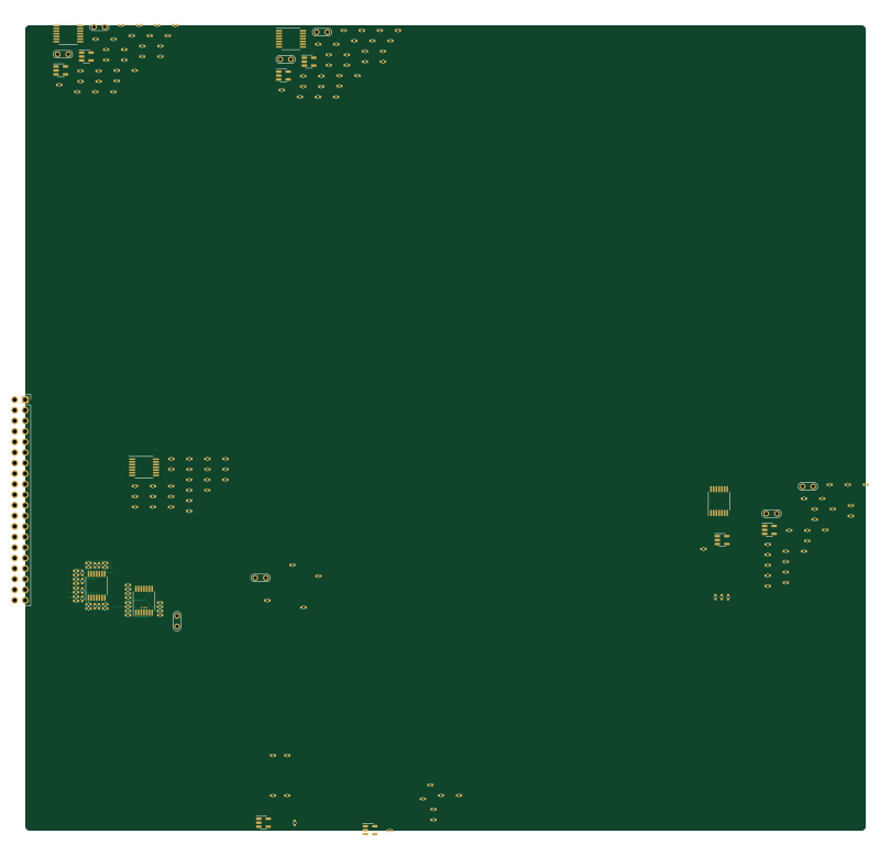
About the Logic analyzer PCB
Logic analyzer is an open source PCB design by tomverbeure, published on GitHub. It is a 4-layer board measuring 202.3 × 193.8 mm, with 183 components from 54 distinct parts.
Other key parts include the EP2C5F484, MIC37302, FT600Q-B-T, W25Q16JVSNIQ and MIC39102. By type, the board carries 88 resistors, 72 capacitors, 14 ICs, 8 test points and 1 connector.
It belongs with the test & measurement designs in this gallery.
From the project
* Agilent - Probing Solutions for Logic Analyzers
* Agilent - Probing Solutions for Logic Analyzers
HP/Agilent 01650-61608 - Sixteen-channel probe lead set Also known as E5383A 40 pins: 16 data input, 1 clk input, 2 +5V, 1 DNC, 18 signal ground, 2 +5V ground RC network: 90k ohm/8.2pF Need board connector that is 0.425" tall 3M 8540-4500PL board connector
* Bidirectional TVS diode for protecting dual-rail power
Main components on the Logic analyzer
Logic analyzer bill of materials (BOM)
183 components, 54 distinct parts — part numbers from the project's BOM.
| Qty | Part | Footprint | Refs |
|---|---|---|---|
| 1 | EP2C5F484 TLV3601 | SOT-23-5 | U1 |
| 1 | MIC37302 TLV3601 | SOT-23-5 | U2 |
| 1 | FT600Q-B-T ADA4891-4 | TSSOP-14_4.4x5mm_P0.65mm | U3 |
| 1 | W25Q16JVSNIQ ADA4891-4 | TSSOP-14_4.4x5mm_P0.65mm | U4 |
| 1 | MIC39102 ADA4891-4 | TSSOP-14_4.4x5mm_P0.65mm | U5 |
| 1 | MIC49150-1.2 TLV3601 | SOT-23-5 | U6 |
| 5 | TLV3601 | SOT-23-5 | U7, U10, U11, U13, U14 |
| 3 | ADA4891-4 | TSSOP-14_4.4x5mm_P0.65mm | U8, U9, U12 |
| 1 | CONN_02X21_ODD_EVEN 3M_8540-4500PL | 3M_8540-4500PL | J1 |
| 8 | TestPoint_2Pole | TestPoint_2Pads_Pitch2.54mm_Drill0.8mm | TP1, TP2, TP3, TP4, TP5, TP6, TP7, TP8 |
| 2 | 100p | C_0402_1005Metric | C1, C29 |
| 6 | 100N 100p | C_0402_1005Metric | C2, C34, C51, C56, C65, C70 |
| 3 | 10n | C_0402_1005Metric | C3, C35, C71 |
| 4 | 100N 10n | C_0402_1005Metric | C4, C52, C57, C66 |
| 2 | 0.1U 1u | C_0402_1005Metric | C5, C6 |
| 1 | 0.1U 30p | C_0402_1005Metric | C7 |
| 1 | 4.7U 30p | C_0402_1005Metric | C8 |
| 11 | 100N 30p | C_0402_1005Metric | C9, C10, C32, C47, C48, C54, C55, C61 +3 |
| 10 | 100N 100n | C_0402_1005Metric | C11, C12, C15, C18, C37, C40, C45, C49 +2 |
| 9 | 100N 10u | C_0402_1005Metric | C13, C14, C16, C38, C41, C46, C50, C60 +1 |
Show 34 more
| Qty | Part | Footprint | Refs |
|---|---|---|---|
| 6 | 100N 70p | C_0402_1005Metric | C17, C22, C39, C42, C43, C44 |
| 1 | 18P 10u | C_0402_1005Metric | C19 |
| 1 | 18P 70p | C_0402_1005Metric | C20 |
| 1 | 4.7U 70p | C_0402_1005Metric | C21 |
| 2 | 100n | C_0402_1005Metric | C23, C27 |
| 1 | 47U 10u | C_0402_1005Metric | C24 |
| 2 | 30p | C_0402_1005Metric | C25, C33 |
| 1 | 47U 30p | C_0402_1005Metric | C26 |
| 1 | 10u | C_0402_1005Metric | C28 |
| 1 | 10U 10n | C_0402_1005Metric | C30 |
| 2 | 1u | C_0402_1005Metric | C31, C72 |
| 4 | 100N 1u | C_0402_1005Metric | C36, C53, C58, C67 |
| 5 | 1.5k | R_0402_1005Metric | R1, R64, R71, R78, R85 |
| 3 | 10K 1.5k | R_0402_1005Metric | R2, R34, R41 |
| 13 | 10K 1k | R_0402_1005Metric | R3, R4, R5, R6, R9, R10, R32, R33 +5 |
| 4 | 10K 20 | R_0402_1005Metric | R7, R8, R37, R44 |
| 2 | 100 | R_0402_1005Metric | R11, R13 |
| 2 | 100 150 | R_0402_1005Metric | R12, R14 |
| 4 | 100 250 | R_0402_1005Metric | R15, R19, R23, R27 |
| 4 | 100 10k | R_0402_1005Metric | R16, R20, R24, R28 |
| 4 | 100 1k | R_0402_1005Metric | R17, R21, R25, R29 |
| 4 | 100 3k | R_0402_1005Metric | R18, R22, R26, R30 |
| 2 | 10K 100 | R_0402_1005Metric | R31, R38 |
| 2 | 10K 150 | R_0402_1005Metric | R36, R43 |
| 1 | 10K 250 | R_0402_1005Metric | R45 |
| 1 | 10K 10k | R_0402_1005Metric | R46 |
| 1 | 10K 3k | R_0402_1005Metric | R48 |
| 3 | 250 | R_0402_1005Metric | R49, R53, R57 |
| 3 | 10k | R_0402_1005Metric | R50, R54, R58 |
| 15 | 1k | R_0402_1005Metric | R51, R55, R59, R62, R63, R65, R69, R70 +7 |
| 3 | 3k | R_0402_1005Metric | R52, R56, R60 |
| 4 | 100 | R_0402_1005Metric | R61, R68, R75, R82 |
| 4 | 150 | R_0402_1005Metric | R66, R73, R80, R87 |
| 4 | 20 | R_0402_1005Metric | R67, R74, R81, R88 |
Logic analyzer design files
The KiCad project lives in the tomverbeure/logic_analyzer repository on GitHub; these links point at the commit this page was built from.
Logic analyzer: common questions
How big is the Logic analyzer PCB?
The Logic analyzer measures 202.3 × 193.8 mm, has 4 copper layers and is 1.60484 mm thick.
How many components are on the Logic analyzer?
183 components, from 54 distinct parts, with part numbers taken from the project's own BOM. The full bill of materials is listed on this page.
Where can I download the Logic analyzer design files?
From the tomverbeure/logic_analyzer repository on GitHub, which has the KiCad layout, the schematic and the BOM; the links under Design files point to each one.
Can I use the Logic analyzer design in my own project?
The repository has no license, so all rights stay with tomverbeure. Use it as a reference, and ask the author before reusing the design.
More boards in logic_analyzer
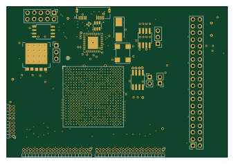
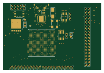
Similar boards
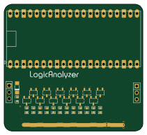
AnalyzerBoxPCB fork
gusmanb
52.7 × 47.9 mm54 parts4LGPL-3.05.0k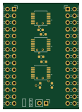
LevelShifter
28.3 × 39.8 mm21 parts2LGPL-3.05.0k
StackLink
52.3 × 10.5 mm5 parts2LGPL-3.05.0k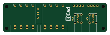
EleLab v2 Frontpanel a
Chrismettal
88 × 25 mm23 parts2LGPL-3.0528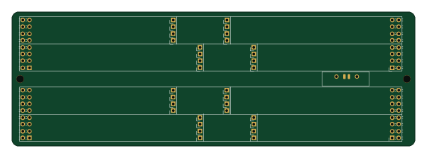
EleLab v2 Bus150
150 × 50 mm37 parts2LGPL-3.0528
EleLab v2 PowerFeed
68 × 50 mm11 parts2LGPL-3.0528