
Rca tester

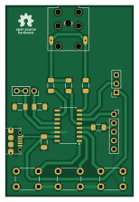
About the Rca tester PCB
Rca tester is an open source RISC-V PCB design by tvecera, published on GitHub under the MIT license. It is a 2-layer board measuring 37.3 × 55.6 mm, with 16 components from 12 distinct parts.
Its main chip is the CH32V002A4M6, from the RISC-V family. By type, the board carries 4 connectors, 4 resistors, 3 switches, 3 capacitors, 1 IC and 1 transistor.
It belongs with the audio designs in this gallery.
From the project
A while ago, I purchased a replica of the Sony Walkman CRT screen, which can be found on Chinese e-shops for a few hundred CZK. The problem is that these screens only support composite video input. I didn't have any device at home capable of generating a composite video signal. T
A while ago, I purchased a replica of the Sony Walkman CRT screen, which can be found on Chinese e-shops for a few hundred CZK. The problem is that these screens only support composite video input. I didn't have any device at home capable of generating a composite video signal. That's why I decided to create a simple and inexpensive RCA tester.
The RCA Tester serves as both a practical tool for testing composite video displays and a demonstration of the rca-library capabilities. It generates standard PAL composite video signals using just a cheap RISC-V microcontroller and a few passive…
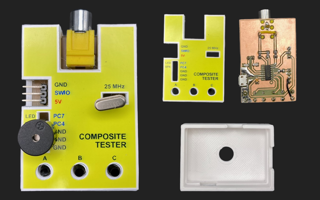
Main components on the Rca tester
Rca tester bill of materials (BOM)
16 components, 12 distinct parts.
| Qty | Part | Footprint | Refs |
|---|---|---|---|
| 1 | CH32V002A4M6 | SOP-16_4.55x10.3mm_P1.27mm | IC1 |
| 1 | 25Mhz | PinSocket_1x03_P2.54mm_Vertical | Q1 |
| 1 | PROG | PinSocket_1x03_P2.54mm_Vertical | J1 |
| 1 | RS-162-DD | RS-162-DD | J2 |
| 1 | GPIO | PinSocket_1x05_P2.54mm_Vertical | J3 |
| 1 | USB Micro | USB_Micro-B_Amphenol_10118194_Horizontal | J4 |
| 3 | SW_Push | SW_PUSH_6mm | SW1, SW2, SW3 |
| 1 | 100n | C_1206_3216Metric_Pad1.33x1.80mm_HandSolder | C1 |
| 2 | 22p | C_1206_3216Metric_Pad1.33x1.80mm_HandSolder | C2, C3 |
| 1 | 470 | R_1206_3216Metric_Pad1.30x1.75mm_HandSolder | R1 |
| 1 | 330 | R_1206_3216Metric_Pad1.30x1.75mm_HandSolder | R2 |
| 2 | 680 | R_1206_3216Metric_Pad1.30x1.75mm_HandSolder | R3, R4 |
Rca tester design files
The KiCad project lives in the tvecera/ch32-projects repository on GitHub; these links point at the commit this page was built from.
Rca tester: common questions
What microcontroller does the Rca tester use?
The Rca tester is built around the CH32V002A4M6, from the RISC-V family.
How big is the Rca tester PCB?
The Rca tester measures 37.3 × 55.6 mm, has 2 copper layers and is 1.6 mm thick.
How many components are on the Rca tester?
16 components, from 12 distinct parts. The full bill of materials is listed on this page.
Where can I download the Rca tester design files?
From the tvecera/ch32-projects repository on GitHub, which has the KiCad layout and the schematic; the links under Design files point to each one.
Can I use the Rca tester design in my own project?
Yes, under the terms of its MIT license, which tvecera chose for the repository.
Can I test firmware for the Rca tester without the hardware?
Yes. HardLabs builds a simulation of the board from its netlist and BOM, so you can run and debug RISC-V firmware against it before you order a PCB.
More boards in ch32-projects
Similar boards
 RISC-V
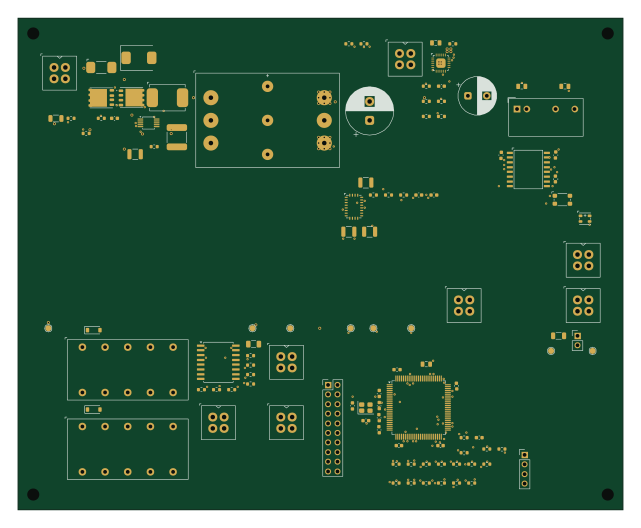
Workbench-1 Controller
Quchaosheng
160 × 130 mm106 parts8LApache-2.0129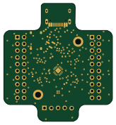 RISC-V
Ch32v003f4u6 with wsled
cnlohr
40.6 × 44.5 mm26 parts2LMIT105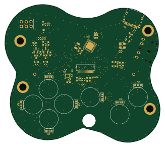 RISC-V
Froggyswadge
81.5 × 72.2 mm92 parts2LMIT105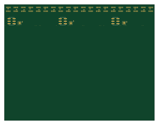 RISC-V
Keytartouch
152.5 × 117.5 mm69 parts2LMIT105 RISC-V
NorthPoleCircuit
Janky-Jingle-Crew
150 × 110 mm46 parts4LNo license62 RISC-V
Osc sg90-v006
OpenServoCore
20.6 × 9.6 mm26 parts4LApache-2.034