
Mpe32board

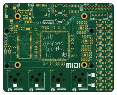
About the Mpe32board PCB
Mpe32board is an open source STM32 PCB design by udu3324, published on GitHub under the GPL-3.0 license. It is a 4-layer board measuring 98 × 79 mm, with 165 components from 33 distinct parts.
Its main chip is the STM32H743IIT, from the STM32 family. Other key parts include the TAC5212IRGER, USBLC6-2P6, TCA9548ARGER, W9812G6KH-75 and LM1117MP-3.3. By type, the board carries 69 resistors, 40 capacitors, 33 connectors, 8 ICs, 7 diodes and 6 switches.
It belongs with the audio designs in this gallery.
From the project
an expressive midi controller that has onboard sound processing with super hackable io
Built in DSP Support for Programs and Sequencer Hacker Header Exposed GPIO Micro-SD Card Support * Onboard SDRAM for extended recording/memory
There is sample code here for trying out the mpe32sensors standalone on the Arduino platform.
Each key is press fit and can also be screwed in with a m3 screw and nut if needed.
Due to my 3d-printer being too small, I have to cut the board in half to print. This is later adhered with uv-glue.
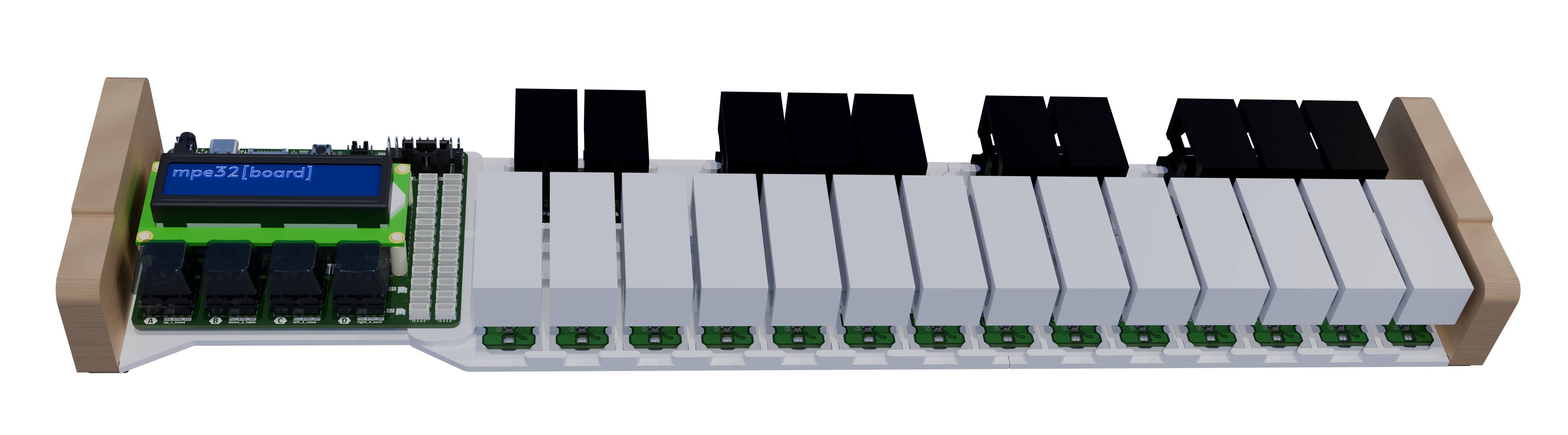
Main components on the Mpe32board
Mpe32board bill of materials (BOM)
165 components, 33 distinct parts — part numbers from the project's BOM.
| Qty | Part | Footprint | Refs |
|---|---|---|---|
| 1 | TAC5212IRGER | VQFN24_RGE_CORNERPADS_TEX-L | U1 |
| 1 | USBLC6-2P6 | SOT-666 | U2 |
| 3 | TCA9548ARGER | Texas_RGE0024C_VQFN-24-1EP_4x4mm_P0.5mm_EP2.1x2.1mm | U4, U5, U6 |
| 1 | STM32H743IIT STM32H743IITx | LQFP-176_24x24mm_P0.5mm | U9 |
| 1 | W9812G6KH-75 | TSOP-II-54_22.2x10.16mm_P0.8mm | U10 |
| 1 | LM1117MP-3.3 | SOT-223-3_TabPin2 | U11 |
| 2 | BSS138 | SOT-23 | Q1, Q2 |
| 1 | CN0295D | CN0295D | CN0295D LCD |
| 1 | FTSH-107-01-F-DV-K-P-TR Conn_ST_STDC14 | CONN-SMD_14P-P1.27_FTSH-107-01-F-DV-K-P-TR | J1 |
| 1 | USB4105-GF-A USB_C_Receptacle_USB2.0_16P | USB_C_Receptacle_GCT_USB4105-xx-A_16P_TopMnt_Horizontal | J2 |
| 1 | DNP Conn_01x01_Socket | PinSocket_1x01_P2.54mm_Vertical | J3 |
| 24 | BM04B-SRSS-TB Conn_01x04 | JST_SH_BM04B-SRSS-TB_1x04-1MP_P1.00mm_Vertical | J4, J5, J6, J7, J8, J9, J10, J11 +16 |
| 1 | 1719710005 Conn_01x05 | Molex_SL_171971-0005_1x05_P2.54mm_Vertical | J44 |
| 1 | DNP Conn_01x04_Socket | PinHeader_1x04_P2.54mm_Vertical | J45 |
| 1 | DNP Conn_02x10_Counter_Clockwise | PinHeader_2x10_P2.54mm_Vertical | J46 |
| 1 | DM3D-SF Micro_SD_Card_Det_Hirose_DM3AT | microSD_HC_Hirose_DM3D-SF | J48 |
| 1 | SJ-3524-SMT-TR AudioJack3_SwitchT | Jack_3.5mm_CUI_SJ-3524-SMT_Horizontal | J49 |
| 2 | DNP SW_Push | SW_PUSH_6mm | SW1, SW2 |
| 4 | DNP SW_Push | MX-Hotswap-1U | SW3, SW4, SW5, SW6 |
| 1 | SS14 | D_SMA | D1 |
Show 13 more
| Qty | Part | Footprint | Refs |
|---|---|---|---|
| 6 | SK6812MINI-E | LED_SK6812MINI-E_3.2x2.8mm_P1.5mm_ReverseMount | D2, D3, D4, D5, D6, D7 |
| 2 | 10uF 1206 X7R 10μF | C_1206_3216Metric | C1, C42 |
| 25 | 100nF 0603 X7R 100nF | C_0603_1608Metric | C2, C3, C4, C5, C6, C7, C8, C9 +17 |
| 2 | 2.2uF 0603 X7R 2.2μF | C_0603_1608Metric | C15, C16 |
| 3 | 1uF 0603 X7R 1μF | C_0603_1608Metric | C21, C28, C43 |
| 3 | 10uF 1206 X7R 10μF | C_0603_1608Metric | C26, C30, C32 |
| 3 | 0.1uF 0603 X7R 0.1μF | C_0603_1608Metric | C27, C29, C31 |
| 2 | 47uF 0603 X7R 47μF | C_0603_1608Metric | C33, C34 |
| 12 | 10k 0603 10kΩ | R_0603_1608Metric | R1, R2, R21, R22, R23, R24, R59, R60 +4 |
| 2 | 5.1k 0603 5.1kΩ | R_0603_1608Metric | R3, R4 |
| 48 | 2.2k 0603 2.2kΩ | R_0603_1608Metric | R5, R6, R7, R8, R9, R10, R11, R12 +40 |
| 2 | 1k 0603 1kΩ | R_0603_1608Metric | R41, R42 |
| 5 | 47k 0603 47kΩ | R_0603_1608Metric | R95, R96, R97, R98, R99 |
Mpe32board design files
The KiCad project lives in the udu3324/mpe32board-midi repository on GitHub; these links point at the commit this page was built from.
Mpe32board: common questions
What microcontroller does the Mpe32board use?
The Mpe32board is built around the STM32H743IIT, from the STM32 family.
How big is the Mpe32board PCB?
The Mpe32board measures 98 × 79 mm, has 4 copper layers and is 1.6 mm thick.
How many components are on the Mpe32board?
165 components, from 33 distinct parts, with part numbers taken from the project's own BOM. The full bill of materials is listed on this page.
Where can I download the Mpe32board design files?
From the udu3324/mpe32board-midi repository on GitHub, which has the KiCad layout, the schematic and the BOM; the links under Design files point to each one.
Can I use the Mpe32board design in my own project?
Yes, under the terms of its GPL-3.0 license, which udu3324 chose for the repository.
Can I test firmware for the Mpe32board without the hardware?
Yes. HardLabs builds a simulation of the board from its netlist and BOM, so you can run and debug STM32 firmware against it before you order a PCB.
More boards in mpe32board-midi

Similar boards
 STM32
STM32LumenPnP Motherboard
opulo-inc
149 × 95 mm296 parts4LCC-BY-SA-4.03.7k STM32
STM32AxxSolder
AxxAxx
39 × 82.5 mm122 parts2LGPL-3.01.7k STM32
STM32LibreVNA
jankae
122 × 98 mm592 parts6LGPL-3.01.6k STM32
STM32AIOC
skuep
21 × 31.5 mm47 parts2LMIT1.4k STM32
STM32Ferris
pierrechevalier83
208.8 × 86.8 mm102 parts2LSHL-2.11.3k STM32
STM32176 pin board
rusefi
61.8 × 73.2 mm76 parts2LGPL-3.01.2k