
Rotator-Controller-V4

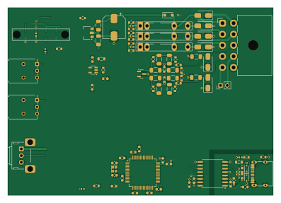
About the Rotator-Controller-V4 PCB
Rotator-Controller-V4 is an open source STM32 PCB design by wa1hco, published on GitHub under the GPL-3.0 license. It is a 2-layer board measuring 99 × 70 mm, with 94 components from 43 distinct parts.
Its main chip is the STM32F405RGTx, from the STM32 family. Other key parts include the ADUM3160, CPC1966, NDP6802SF-50 and AP2112K-3.3. By type, the board carries 34 capacitors, 26 resistors, 17 diodes, 7 ICs, 3 connectors and 2 switches.
From the project
Clean slate rebuild of full featured rotator controller.
KiCad 9 project for the shack-side antenna rotator controller. The files in this directory are the imported CPC1966 design: STM32F405RGT6 in LQFP-64, ADuM4160 isolated USB, and three CPC1966 AC solid-state relays (CW, CCW, brake).
That MCU is not the build target. The accepted part is an STM32F407VGT6 (LQFP-100, LCSC C12345) with a LAN8720A RMII PHY, and Ethernet is standard. See docs/decisions/0014-stm32f407-lan8720.md and docs/design/mcu-ethernet-lcsc.md. The schematic and PCB are intentionally not edited for that change. The MCU area was barely routed, so the next layout pass replaces the…
Main components on the Rotator-Controller-V4
Rotator-Controller-V4 bill of materials (BOM)
94 components, 43 distinct parts.
| Qty | Part | Footprint | Refs |
|---|---|---|---|
| 1 | ADUM3160 | SOIC-16W_7.5x10.3mm_P1.27mm | U1 |
| 1 | STM32F405RGTx | LQFP-64_10x10mm_P0.5mm | U2 |
| 3 | CPC1966 | CPC1966 | U3, U4, U5 |
| 1 | NDP6802SF-50 | SOT-89-3 | U6 |
| 1 | AP2112K-3.3 | SOT-23-5 | U7 |
| 1 | 12M | Crystal_SMD_2016-4Pin_2.0x1.6mm | Y1 |
| 1 | USB-C 2.0 16P | USB_C_Receptacle_G-Switch_GT-USB-7010ASV | J1 |
| 1 | Motor Cap | PinHeader_1x02_P2.54mm_Vertical | J2 |
| 1 | Rotator | TE_MATE-N-LOK_1-770971-x_2x05_P4.14mm_Horizontal | J3 |
| 1 | ~ | LP4-EP | O1 |
| 1 | Az_Preset | Potentiometer_Alps_RK09K_Single_Horizontal | RV1 |
| 2 | CW | SW_NKK_BB15AH | SW1, SW2 |
| 2 | MM3Z3V6 | D_SOD-323 | D1, D2 |
| 1 | Motor | LED_0402_1005Metric | D3 |
| 1 | 5V_GRN | LED_0402_1005Metric | D4 |
| 1 | White | LED_0402_1005Metric | D5 |
| 1 | 2BZX84C3V6 | SOT-23 | D6 |
| 1 | 1N4004 | D_SOD-123F | D7 |
| 1 | Left | LED_0402_1005Metric | D8 |
| 1 | Right | LED_0402_1005Metric | D9 |
Show 23 more
| Qty | Part | Footprint | Refs |
|---|---|---|---|
| 1 | Brake | LED_0402_1005Metric | D10 |
| 1 | 26VAC | LED_0402_1005Metric | D11 |
| 4 | SMAJ90CA | D_SMA | D12, D13, D14, D15 |
| 2 | SMAJ10CA | D_SMA | D16, D17 |
| 2 | FerriteBead_Small | L_0805_2012Metric | FB1, FB2 |
| 2 | 47p | C_0603_1608Metric | C1, C3 |
| 4 | .1u | C_0603_1608Metric | C2, C4, C7, C9 |
| 5 | 10u | C_0603_1608Metric | C5, C12, C15, C17, C33 |
| 2 | 0.1u | C_0603_1608Metric | C6, C18 |
| 5 | 1u | C_0603_1608Metric | C8, C11, C14, C16, C34 |
| 2 | 20p | C_0603_1608Metric | C10, C13 |
| 1 | 120u 100V | CP_Elec_8x10 | C19 |
| 8 | 0.1 2% | C_1206_3216Metric_Pad1.33x1.80mm_HandSolder | C20, C21, C22, C23, C24, C25, C27, C28 |
| 2 | 1u | C_1206_3216Metric_Pad1.33x1.80mm_HandSolder | C26, C30 |
| 3 | 0.1 200V | C_1206_3216Metric_Pad1.33x1.80mm_HandSolder | C29, C31, C32 |
| 2 | 5K1 | R_0603_1608Metric | R1, R2 |
| 2 | 1K5 | R_0603_1608Metric | R3, R4 |
| 2 | 27 | R_0402_1005Metric | R5, R6 |
| 9 | 1k | R_0603_1608Metric | R7, R11, R12, R13, R14, R15, R16, R22 +1 |
| 2 | 10K | R_0603_1608Metric | R8, R26 |
| 6 | 27K 1% | R_0603_1608Metric | R9, R10, R18, R19, R20, R21 |
| 1 | 4K7 | R_0603_1608Metric | R17 |
| 2 | 360 | R_0603_1608Metric | R24, R25 |
Rotator-Controller-V4 design files
The KiCad project lives in the wa1hco/rotator_controller repository on GitHub; these links point at the commit this page was built from.
Rotator-Controller-V4: common questions
What microcontroller does the Rotator-Controller-V4 use?
The Rotator-Controller-V4 is built around the STM32F405RGTx, from the STM32 family.
How big is the Rotator-Controller-V4 PCB?
The Rotator-Controller-V4 measures 99 × 70 mm, has 2 copper layers and is 1.6 mm thick.
How many components are on the Rotator-Controller-V4?
94 components, from 43 distinct parts. The full bill of materials is listed on this page.
Where can I download the Rotator-Controller-V4 design files?
From the wa1hco/rotator_controller repository on GitHub, which has the KiCad layout and the schematic; the links under Design files point to each one.
Can I use the Rotator-Controller-V4 design in my own project?
Yes, under the terms of its GPL-3.0 license, which wa1hco chose for the repository.
Can I test firmware for the Rotator-Controller-V4 without the hardware?
Yes. HardLabs builds a simulation of the board from its netlist and BOM, so you can run and debug STM32 firmware against it before you order a PCB.
More boards in rotator_controller
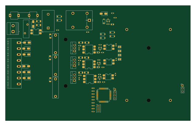
Similar boards
 STM32
LumenPnP Motherboard
opulo-inc
149 × 95 mm296 parts4LCC-BY-SA-4.03.7k STM32
Type g
google
169 × 30 mm24 parts2LApache-2.02.9k STM32
Main panel
234 × 84 mm26 parts4LApache-2.02.9k STM32
Base
52.3 × 52.3 mm36 parts2LApache-2.02.9k STM32
Type a
150 × 30 mm14 parts2LApache-2.02.9k STM32
Type c
188 × 30 mm17 parts2LApache-2.02.9k