
Pseusplit

About the Pseusplit PCB
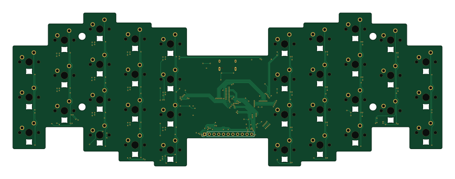
Pseusplit is an open source STM32 PCB design by waffle87, published on GitHub under the CERN-OHL-P-2.0 license. It is a 2-layer board measuring 231.4 × 82.6 mm, with 146 components from 63 distinct parts.
Its main chip is the STM32G0B1CBTX, from the STM32 family. Other key parts include the IS31FL3733-QF, XC6206PXXXMR and SRV05-4. By type, the board carries 38 diodes, 36 LEDs, 17 capacitors, 10 resistors, 4 ICs and 2 connectors.
It belongs with the keyboards and displays & leds designs in this gallery.
From the project
Pseudo-split Keyboard PCB
A pseudo-split keyboard with a trackpad or LCD display and per-key RGB
* The switch plate PCB is designed for a single half of the keyboard (and is reversible), meaning ordering a quantity of 10 will be enough to cover 5 keyboards.
1. Upload the appropriate Gerber files described above 2. Set PCB quantity and colour as desired 3. For PCB assembly, choose Economic PCBA type and Bottom Side for assembly side 4. Upload the BOM and CPL files 5. Ensure the correct components have been selected, and all are in stock. An effort has been made to choose as few extended components as possible, but…
Main components on the Pseusplit
Pseusplit bill of materials (BOM)
146 components, 63 distinct parts — part numbers from the project's BOM.
| Qty | Part | Footprint | Refs |
|---|---|---|---|
| 1 | IS31FL3733-QF | QFN-48-1EP_6x6mm_P0.4mm_EP4.2x4.2mm | U1 |
| 1 | XC6206PXXXMR XC6206PxxxMR | SOT-23-3 | U2 |
| 1 | STM32G0B1CBTX STM32G0B1CBTx | LQFP-48_7x7mm_P0.5mm | U4 |
| 1 | SRV05-4 | SOT-23-6-routable | U5 |
| 1 | DTC123J | SOT-23 | Q1 |
| 1 | USB_C_RECEPTACLE_USB2.0_14P USB_C_Receptacle_USB2.0_14P | USB_C_Receptacle_HRO_TYPE-C-31-M-12 | J1 |
| 1 | ST7789 320x240/TPS43 | PinHeader_1x11_P2.54mm_Vertical | J3 |
| 1 | 500MA 500mA | Fuse_1206_3216Metric | F1 |
| 1 | Q | SW_MX_1u | MX1 |
| 1 | W | SW_MX_1u | MX2 |
| 1 | E | SW_MX_1u | MX3 |
| 1 | R | SW_MX_1u | MX4 |
| 1 | T | SW_MX_1u | MX5 |
| 1 | A | SW_MX_1u | MX6 |
| 1 | S | SW_MX_1u | MX7 |
| 1 | D | SW_MX_1u | MX8 |
| 1 | F | SW_MX_1u | MX9 |
| 1 | G | SW_MX_1u | MX10 |
| 1 | Z | SW_MX_1u | MX11 |
| 1 | X | SW_MX_1u | MX12 |
Show 43 more
| Qty | Part | Footprint | Refs |
|---|---|---|---|
| 1 | C | SW_MX_1u | MX13 |
| 1 | V | SW_MX_1u | MX14 |
| 1 | B | SW_MX_1u | MX15 |
| 1 | Y | SW_MX_1u | MX16 |
| 1 | H | SW_MX_1u | MX17 |
| 1 | N | SW_MX_1u | MX18 |
| 1 | U | SW_MX_1u | MX19 |
| 1 | J | SW_MX_1u | MX20 |
| 1 | M | SW_MX_1u | MX21 |
| 1 | I | SW_MX_1u | MX22 |
| 1 | K | SW_MX_1u | MX23 |
| 1 | , | SW_MX_1u | MX24 |
| 1 | O | SW_MX_1u | MX25 |
| 1 | L | SW_MX_1u | MX26 |
| 1 | . | SW_MX_1u | MX27 |
| 1 | P | SW_MX_1u | MX28 |
| 1 | ; | SW_MX_1u | MX29 |
| 1 | / | SW_MX_1u | MX30 |
| 1 | T1 | SW_MX_1u | MX31 |
| 1 | T2 | SW_MX_1u | MX32 |
| 1 | T3 | SW_MX_1u | MX33 |
| 1 | T4 | SW_MX_1u | MX34 |
| 1 | T5 | SW_MX_1u | MX35 |
| 1 | T6 | SW_MX_1u | MX36 |
| 1 | C318884 Reset_SW | SW_SPST_SKQG_WithStem | SW1 |
| 36 | MX_LED_6028R | LED_MX_6028R | LED1, LED2, LED3, LED4, LED5, LED6, LED7, LED8 +28 |
| 36 | D_45DEG D_45deg | D_SOD-123 | D1, D2, D3, D4, D5, D6, D7, D8 +28 |
| 1 | 1N4148 | D_SOD-123 | D37 |
| 1 | LED | LED_0805_2012Metric | D40 |
| 4 | 0.47U 0.47u | C_0805_2012Metric | C1, C2, C4, C6 |
| 3 | 0.1U 0.1u | C_0805_2012Metric | C3, C5, C7 |
| 1 | 22U 22u | CP_EIA-3216-18_Kemet-A | C8 |
| 2 | 4.7N 4.7n | C_0805_2012Metric | C9, C12 |
| 2 | 1u | C_0805_2012Metric | C10, C11 |
| 1 | 10U 10u | C_0805_2012Metric | C13 |
| 2 | 100N 100n | C_0805_2012Metric | C14, C16 |
| 2 | 4.7U 4.7u | C_0805_2012Metric | C17, C18 |
| 1 | 20K 20k | R_0805_2012Metric | R1 |
| 2 | 100K 100k | R_0805_2012Metric | R2, R11 |
| 1 | 10K 10k | R_0805_2012Metric | R3 |
| 2 | 2k | R_0805_2012Metric | R4, R5 |
| 1 | 1M | R_0805_2012Metric | R6 |
| 3 | 5.1K 5.1k | R_0805_2012Metric | R7, R8, R12 |
Pseusplit design files
The KiCad project lives in the waffle87/pseusplit repository on GitHub; these links point at the commit this page was built from.
- Layoutpseusplit.kicad_pcb
- Schematicpseusplit.kicad_sch
- BOMproduction/bom.csv
Pseusplit: common questions
What microcontroller does the Pseusplit use?
The Pseusplit is built around the STM32G0B1CBTX, from the STM32 family.
How big is the Pseusplit PCB?
The Pseusplit measures 231.4 × 82.6 mm, has 2 copper layers and is 1.6 mm thick.
How many components are on the Pseusplit?
146 components, from 63 distinct parts, with part numbers taken from the project's own BOM. The full bill of materials is listed on this page.
Where can I download the Pseusplit design files?
From the waffle87/pseusplit repository on GitHub, which has the KiCad layout, the schematic and the BOM; the links under Design files point to each one.
Can I use the Pseusplit design in my own project?
Yes, under the terms of its CERN-OHL-P-2.0 license, which waffle87 chose for the repository.
Can I test firmware for the Pseusplit without the hardware?
Yes. HardLabs builds a simulation of the board from its netlist and BOM, so you can run and debug STM32 firmware against it before you order a PCB.
Similar boards
 STM32
STM32LumenPnP Motherboard
opulo-inc
149 × 95 mm296 parts4LCC-BY-SA-4.03.7k STM32
STM32AxxSolder
AxxAxx
39 × 82.5 mm122 parts2LGPL-3.01.7k STM32
STM32LibreVNA
jankae
122 × 98 mm592 parts6LGPL-3.01.6k STM32
STM32AIOC
skuep
21 × 31.5 mm47 parts2LMIT1.4k STM32
STM32Ferris
pierrechevalier83
208.8 × 86.8 mm102 parts2LSHL-2.11.3k STM32
STM32176 pin board
rusefi
61.8 × 73.2 mm76 parts2LGPL-3.01.2k