
Analog separate

About the Analog separate PCB
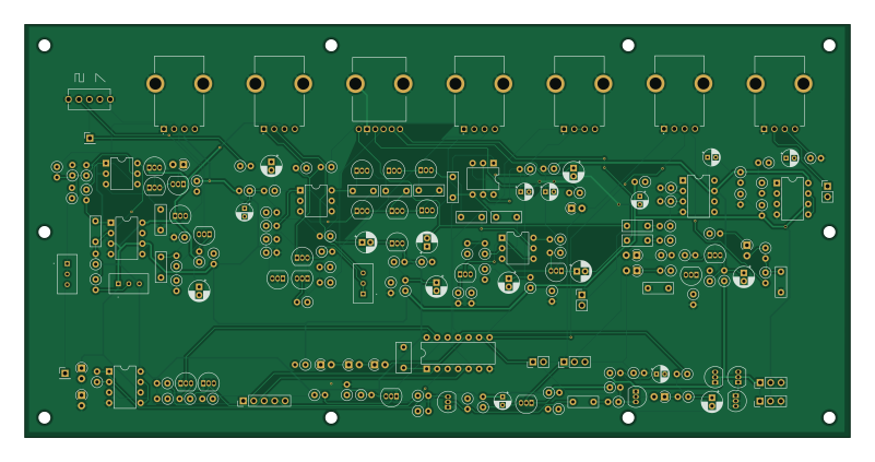
Analog separate is an open source PCB design by wakimizufu, published on GitHub. It is a 2-layer board measuring 200 × 100 mm, with 185 components from 52 distinct parts.
Other key parts include the AN6562, 4066 and CA3080A. By type, the board carries 77 resistors, 32 transistors, 31 capacitors, 11 diodes, 9 connectors and 4 ICs.
Main components on the Analog separate
Analog separate bill of materials (BOM)
185 components, 52 distinct parts — part numbers from the project's BOM.
| Qty | Part | Footprint | Refs |
|---|---|---|---|
| 1 | AN6562 | DIP-8_W7.62mm | IC11 |
| 1 | AN6562 | DIP-8_W7.62mm | IC11_1 |
| 1 | 4066 | DIP-14_W7.62mm | IC12 |
| 1 | CA3080A | DIP-8_W7.62mm | IC15 |
| 7 | PNP | TO-92_Inline | Q8, Q9, Q10, Q27, Q31, Q36, Q38 |
| 19 | NPN | TO-92_Inline | Q11, Q13, Q14, Q15, Q16, Q17, Q18, Q19 +11 |
| 4 | HN4A06J(TE85L,F) HN1C01FU-GR,LF_6P DIP | DIP-6_W7.62mm | Q12, Q21, Q22, Q26 |
| 2 | NJFET | TO-92_Inline | Q28, Q39 |
| 2 | Conn_01x03_Pin | PinHeader_1x03_P2.54mm_Vertical | J1, J5 |
| 1 | Conn_01x05_Pin | PinHeader_1x05_P2.54mm_Vertical | J2 |
| 3 | CONN_01X02_PIN Conn_01x02_Pin | PinHeader_1x02_P2.54mm_Vertical | J3, J4, J8 |
| 1 | CONN_01X03_PIN Conn_01x03_Pin | PinHeader_1x03_P2.54mm_Vertical | J7 |
| 2 | CONN_01X01_PIN Conn_01x01_Pin | PinHeader_1x01_P2.54mm_Vertical | J9, J13 |
| 1 | 2MS1T1B4VS2QES | 2MS1T1B4VS2QES | SW1 |
| 1 | 3296W-1-502A 500K | 3296W1502A | TM3 |
| 1 | 3296W-1-502A 50K | 3296W1502A | TM4 |
| 1 | 3296W-1-502A 5K | 3296W1502A | TM5 |
| 2 | 10uF/16V | CP_Radial_D4.0mm_P2.00mm | VCA_C_1, VCA_C_2 |
| 1 | Opamp_Dual | DIP-8_W7.62mm | VCA_IC_1 |
| 1 | 10K | R_Axial_DIN0207_L6.3mm_D2.5mm_P2.54mm_Vertical | VCA_R1 |
Show 32 more
| Qty | Part | Footprint | Refs |
|---|---|---|---|
| 1 | 100 | R_Axial_DIN0207_L6.3mm_D2.5mm_P2.54mm_Vertical | VCA_R2 |
| 2 | 47K | R_Axial_DIN0207_L6.3mm_D2.5mm_P2.54mm_Vertical | VCA_R3, VCA_R5 |
| 3 | 100K | R_Axial_DIN0207_L6.3mm_D2.5mm_P2.54mm_Vertical | VCA_R4, VCA_R6, VCA_R7 |
| 2 | PTV111-3420A-A103 50K(B) | PTV1113420AA103 | VR2, VR7 |
| 2 | PTV111-3420A-A103 50K(A) | PTV1113420AA103 | VR3, VR5 |
| 1 | PTV112-4420A-A504 50K(B)2連 | PTV1124420AA504 | VR4 |
| 1 | PTV111-3420A-A103 1M(A) | PTV1113420AA103 | VR6 |
| 1 | PTV111-3420A-A103 10K(B) | PTV1113420AA103 | VR8 |
| 11 | D | D_A-405_P2.54mm_Vertical_AnodeUp | D24, D25, D26, D27, D28, D29, D31, D32 +3 |
| 4 | 0.01UF 0.01uF | C_Rect_L7.2mm_W2.5mm_P5.00mm_FKS2_FKP2_MKS2_MKP2 | C10, C20, C21, C33 |
| 10 | 1UF/50V 1uF/50V | CP_Radial_D5.0mm_P2.00mm | C11, C13, C14, C15, C17, C22, C23, C29 +2 |
| 4 | 10UF/16V 10uF/16V | CP_Radial_D4.0mm_P2.00mm | C16, C30, C37, C72 |
| 1 | 0.018UF 0.018uF | C_Rect_L7.2mm_W2.5mm_P5.00mm_FKS2_FKP2_MKS2_MKP2 | C18 |
| 4 | 0.033UF 0.033uF | C_Rect_L7.2mm_W2.5mm_P5.00mm_FKS2_FKP2_MKS2_MKP2 | C19, C24, C26, C36 |
| 3 | 0.1UF 0.1uF | C_Rect_L7.2mm_W2.5mm_P5.00mm_FKS2_FKP2_MKS2_MKP2 | C25, C27, C41 |
| 2 | 47UF/16V 47uF/16V | CP_Radial_D4.0mm_P2.00mm | C28, C55 |
| 1 | 0.001UF 0.001uF | C_Rect_L7.2mm_W2.5mm_P5.00mm_FKS2_FKP2_MKS2_MKP2 | C34 |
| 1 | 0.22UF 0.22uF | C_Rect_L7.2mm_W3.5mm_P5.00mm_FKS2_FKP2_MKS2_MKP2 | C35 |
| 1 | 0.047UF 0.047uF | C_Rect_L7.2mm_W2.5mm_P5.00mm_FKS2_FKP2_MKS2_MKP2 | C54 |
| 21 | 10K | R_Axial_DIN0207_L6.3mm_D2.5mm_P2.54mm_Vertical | R34, R36, R47, R61, R64, R65, R94, R96 +13 |
| 16 | 100K | R_Axial_DIN0207_L6.3mm_D2.5mm_P2.54mm_Vertical | R35, R59, R66, R72, R73, R92, R93, R99 +8 |
| 8 | 22K | R_Axial_DIN0207_L6.3mm_D2.5mm_P2.54mm_Vertical | R45, R110, R111, R117, R120, R134, R146, R151 |
| 2 | 47K | R_Axial_DIN0207_L6.3mm_D2.5mm_P2.54mm_Vertical | R46, R119 |
| 5 | 220K | R_Axial_DIN0207_L6.3mm_D2.5mm_P2.54mm_Vertical | R62, R63, R103, R121, R131 |
| 13 | 2.2K | R_Axial_DIN0207_L6.3mm_D2.5mm_P2.54mm_Vertical | R67, R68, R69, R70, R71, R98, R104, R107 +5 |
| 1 | 1M | R_Axial_DIN0207_L6.3mm_D2.5mm_P2.54mm_Vertical | R91 |
| 4 | 100 | R_Axial_DIN0207_L6.3mm_D2.5mm_P2.54mm_Vertical | R95, R130, R132, R152 |
| 2 | 1K(TEMPCO) | R_Axial_DIN0207_L6.3mm_D2.5mm_P2.54mm_Vertical | R100, R100_1 |
| 1 | 27K | R_Axial_DIN0207_L6.3mm_D2.5mm_P2.54mm_Vertical | R106 |
| 1 | 1.5M | R_Axial_DIN0207_L6.3mm_D2.5mm_P2.54mm_Vertical | R123 |
| 1 | 68K | R_Axial_DIN0207_L6.3mm_D2.5mm_P2.54mm_Vertical | R138 |
| 2 | 22 | R_Axial_DIN0207_L6.3mm_D2.5mm_P2.54mm_Vertical | R147, R150 |
Analog separate design files
The KiCad project lives in the wakimizufu/TBSEQ repository on GitHub; these links point at the commit this page was built from.
Analog separate: common questions
How big is the Analog separate PCB?
The Analog separate measures 200 × 100 mm, has 2 copper layers and is 1.6 mm thick.
How many components are on the Analog separate?
185 components, from 52 distinct parts, with part numbers taken from the project's own BOM. The full bill of materials is listed on this page.
Where can I download the Analog separate design files?
From the wakimizufu/TBSEQ repository on GitHub, which has the KiCad layout, the schematic and the BOM; the links under Design files point to each one.
Can I use the Analog separate design in my own project?
The repository has no license, so all rights stay with wakimizufu. Use it as a reference, and ask the author before reusing the design.
More boards in TBSEQ
 RP2040/RP2350
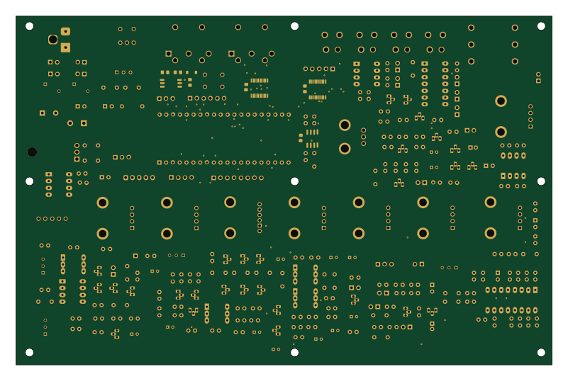
MainBorad R1
200 × 130.3 mm258 parts2LNo license0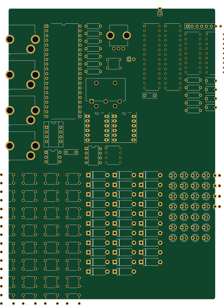 RP2040/RP2350
Controll
110.6 × 155 mm135 parts2LNo license0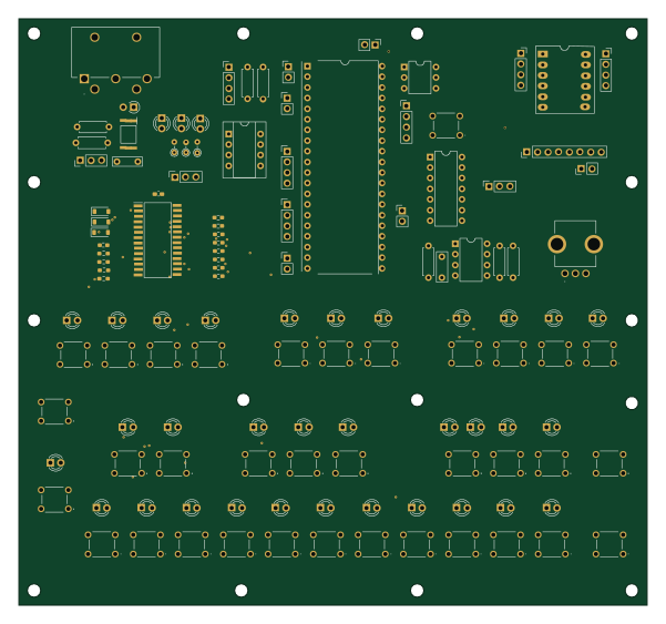 RP2040/RP2350
HT16K33Panel
150 × 140 mm126 parts2LNo license0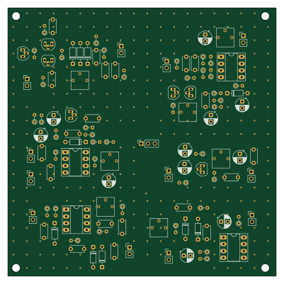
TestODDT
100 × 100 mm113 parts2LNo license0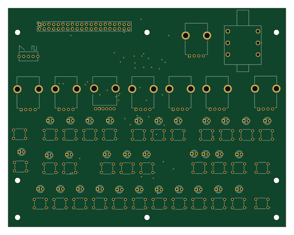
FrontPanel
150 × 118 mm95 parts2LNo license0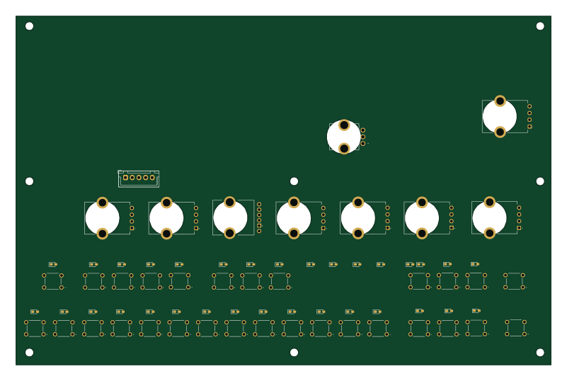
PanelBoard
200 × 130.3 mm90 parts2LNo license0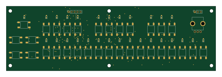
RythemPanelBoard
180 × 55.4 mm81 parts2LNo license0
LM13700 VCA
100 × 84 mm74 parts2LNo license0
LM13700 Overdrive
80 × 70.5 mm46 parts2LNo license0
USBPD12VModule
25 × 34.5 mm17 parts2LNo license0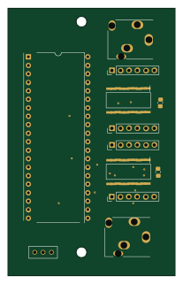 RP2040/RP2350
SyncBoard
50 × 80 mm12 parts2LNo license0