
Smartmeter p1 board

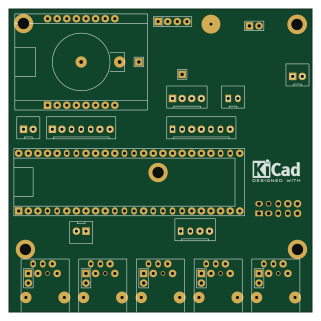
About the Smartmeter p1 board
Smartmeter p1 board is an open source ESP8266 PCB design by weigu1, published on GitHub under the GPL-3.0 license. It is a board measuring 80 × 80 mm, with 71 components from 33 distinct parts.
Its main chip is the WEMOS_D1_mini, from the ESP8266 family. By type, the board carries 26 resistors, 18 connectors, 11 transistors, 7 capacitors, 5 jumpers and 1 battery holder.
It belongs with the iot & wireless designs in this gallery.
From the project
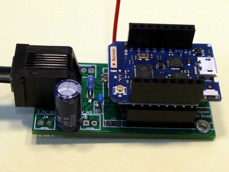
Because of the EU Energy Efficiency Directive from 2012 the gas and electricity Distribution System Operators (DSO) in Luxembourg replaced there gas and energy meters with smartmeters (named smarty :() from Sagemcom (T210-D).
Because of the EU Energy Efficiency Directive from 2012 the gas and electricity Distribution System Operators (DSO) in Luxembourg replaced there gas and energy meters with smartmeters (named smarty :() from Sagemcom (T210-D).
As it seems the same smartmeters are deployed in Sweden, parts of Austria and the Netherlands.
These smartmeters have a user port that delivers 10 second data (RJ12 connector under the green lid). The P1 data output communication protocol and format is specified in the Dutch Smart Meter Requirements v5.0.2 . The solution deployed in Luxembourg includes an additional…
Smartmeter p1 board bill of materials (BOM)
71 components, 33 distinct parts.
| Qty | Part | Footprint | Refs |
|---|---|---|---|
| 11 | 2N7002 | SOT-23 | Q1, Q2, Q3, Q4, Q5, Q6, Q7, Q8 +3 |
| 1 | Smartmeter1 | WRJ12 | J1 |
| 1 | Smartmeter2 | WRJ12 | J2 |
| 1 | Smartmeter3 | WRJ12 | J3 |
| 1 | Smartmeter4 | WRJ12 | J4 |
| 1 | Smartmeter5 | WRJ12 | J5 |
| 1 | W5500_2x5 | WW5500 | J6 |
| 1 | Exp_Header2 | WSIL4_SL | J7 |
| 1 | Exp_Header3 | WSIL7_SL | J8 |
| 1 | Exp_Header4 | WSIL7_SL | J9 |
| 1 | 3.3V_H1 | WSIL2_SL | J10 |
| 1 | 5V_H1 | WSIL2_SL | J11 |
| 1 | 5V_H2 | WSIL2_SL | J12 |
| 1 | I2C_Header | WSIL4_SL | J13 |
| 1 | Exp_Header1 | WSIL2_SL | J14 |
| 1 | BAT+ | WSIL1 | J15 |
| 1 | RX6 | WSIL1 | J16 |
| 1 | GND_H3 | WSIL2 | J17 |
| 1 | rainwater | WSIL4 | J18 |
| 1 | C1 | WPin_3mm | AD1 |
Show 13 more
| Qty | Part | Footprint | Refs |
|---|---|---|---|
| 1 | WBATTERY | WBAT | BT1 |
| 5 | Jump | WSIL2 | JP1, JP2, JP3, JP4, JP5 |
| 1 | TEENSY36 | WTEENSY36 | T1 |
| 1 | WEMOS_D1_mini | WWEMOSD1 | W1 |
| 4 | 100nF | W0805 | C1, C2, C3, C7 |
| 2 | 10uF | W1206 | C4, C5 |
| 1 | 100pF | W0805 | C6 |
| 5 | 220 | W0805 | R1, R2, R3, R4, R5 |
| 5 | 1k | W0805 | R6, R7, R8, R9, R10 |
| 7 | 10k | W0805 | R11, R12, R13, R14, R15, R25, R26 |
| 6 | 15k | W0805 | R16, R17, R18, R19, R20, R24 |
| 2 | 1.8k | W0805 | R21, R22 |
| 1 | 0 | W1206 | R23 |
Smartmeter p1 board design files
The KiCad project lives in the weigu1/SmartyReader repository on GitHub; these links point at the commit this page was built from.
Smartmeter p1 board: common questions
What microcontroller does the Smartmeter p1 board use?
The Smartmeter p1 board is built around the WEMOS_D1_mini, from the ESP8266 family.
How big is the Smartmeter p1 board?
The Smartmeter p1 board measures 80 × 80 mm and is 1.6002 mm thick.
How many components are on the Smartmeter p1 board?
71 components, from 33 distinct parts. The full bill of materials is listed on this page.
Where can I download the Smartmeter p1 board design files?
From the weigu1/SmartyReader repository on GitHub, which has the KiCad layout; the links under Design files point to each one.
Can I use the Smartmeter p1 board design in my own project?
Yes, under the terms of its GPL-3.0 license, which weigu1 chose for the repository.
Can I test firmware for the Smartmeter p1 board without the hardware?
Yes. HardLabs builds a simulation of the board from its netlist and BOM, so you can run and debug ESP8266 firmware against it before you order a PCB.
More boards in SmartyReader
Similar boards
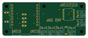 ESP8266
ControllerCircuit
stuartpittaway
75 × 30 mm20 parts2LCC-BY-NC-4.01.1k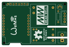 ESP8266
HASwitchPlate
aderusha
60 × 40 mm8 parts2LMIT738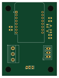 ESP8266
RatGDO-OpenSource-D1Mini-ESP8266
Kaldek
47.8 × 63.3 mm12 parts2LMIT506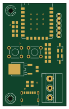 ESP8266
Goatgdo
32.9 × 53.3 mm23 parts2LMIT506 ESP8266
RatGDO-OpenSource-Bare-ESP8266
55 × 82.7 mm20 parts2LMIT506 ESP8266
Iaq board
nkitanov
70.1 × 43.2 mm17 parts2LNo license398