
Telematics device

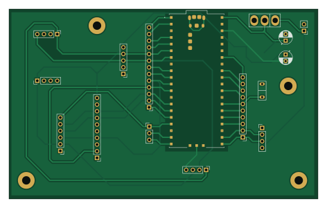
About the Telematics device PCB
Telematics device is an open source PCB design by Yadnik1, published on GitHub. It is a 2-layer board measuring 117.8 × 72.3 mm, with 17 components from 17 distinct parts.
Other key parts include the SC0915 and AZ1117-3.3. By type, the board carries 11 connectors, 2 ICs, 2 switches and 2 capacitors.
It belongs with the sensors and displays & leds designs in this gallery.
From the project
Developed a cost-effective telematics device for automobiles, capable of enabling user-based insurance models to save up to 30% on premiums. Features include a two-layer PCB design in KiCad, efficient firmware in C with CMake, and advanced noise reduction in IMU sensors using Python.
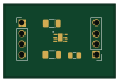
1) The project involved the use of AECQ100 grade IMU and Temperature and Humidity sensors (SHT30A) sensors for which custom breakout boards had to be created in KiCAD and hold soldered: #### Breakout Board PCB of AEC-Q100 compliant SHT-30A Temperature and Humidity Sensor #### Breakout Board PCB of AEC-Q100 compliant 6-DOF IMU ASM330LHHXTR #### Fabricated Breakout Boards with IC
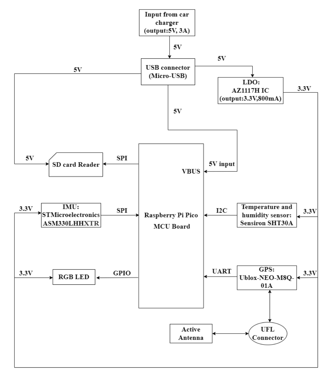
Main components on the Telematics device
Telematics device bill of materials (BOM)
17 components, 17 distinct parts — part numbers from the project's BOM.
| Qty | Part | Footprint | Refs |
|---|---|---|---|
| 1 | SC0915 | MODULE_SC0915 | U1 |
| 1 | AZ1117-3.3 | DPAK457P1010X238-3N | U2 |
| 1 | CONN_01X04 DS3231_RTC | PinHeader_1x05_P2.54mm_Vertical | J1 |
| 1 | CONN_01X04 OLED_SCREEN | PinHeader_1x04_P2.54mm_Vertical | J2 |
| 1 | MPU9250 | PinHeader_1x10_P2.54mm_Vertical | J3 |
| 1 | MicroSD card module | PinHeader_1x06_P2.54mm_Vertical | J4 |
| 1 | SHT30A_CONN | PinHeader_1x04_P2.54mm_Vertical | J5 |
| 1 | SHT30A_PWR | PinHeader_1x04_P2.54mm_Vertical | J6 |
| 1 | Conn_01x02_Male | PinHeader_1x02_P2.54mm_Vertical | J13 |
| 1 | GPS module | PinHeader_1x04_P2.54mm_Vertical | J17 |
| 1 | Conn_01x13_external | PinHeader_1x13_P2.54mm_Vertical | J26 |
| 1 | Conn_01x03_external | PinHeader_1x03_P2.54mm_Vertical | J27 |
| 1 | Conn_01x10_external | PinHeader_1x10_P2.54mm_Vertical | J28 |
| 1 | SW_SPDT | SPDT switch | SW1 |
| 1 | SW_Push | Push button | SW2 |
| 1 | 100N 10u | CP_Radial_D5.0mm_P2.50mm | C1 |
| 1 | 22u | CP_Radial_D5.0mm_P2.50mm | C2 |
Telematics device design files
The KiCad project lives in the Yadnik1/Low-Cost-Telematics-Device repository on GitHub; these links point at the commit this page was built from.
Telematics device: common questions
How big is the Telematics device PCB?
The Telematics device measures 117.8 × 72.3 mm, has 2 copper layers and is 1.6 mm thick.
How many components are on the Telematics device?
17 components, from 17 distinct parts, with part numbers taken from the project's own BOM. The full bill of materials is listed on this page.
Where can I download the Telematics device design files?
From the Yadnik1/Low-Cost-Telematics-Device repository on GitHub, which has the KiCad layout, the schematic and the BOM; the links under Design files point to each one.
Can I use the Telematics device design in my own project?
The repository has no license, so all rights stay with Yadnik1. Use it as a reference, and ask the author before reusing the design.
More boards in Low-Cost-Telematics-Device

Similar boards

LevelShifterBreakout
scottbez1
15.2 × 20.3 mm5 parts2LApache-2.022.2k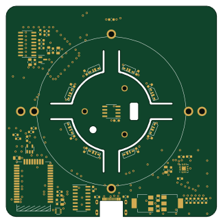
View base
81.2 × 81.2 mm81 parts2LApache-2.022.2k
View screen
35 × 35 mm12 parts2LApache-2.022.2k
BM28B0.6-24DSBreakout
15.2 × 35.6 mm3 parts2LApache-2.022.2k
ChainlinkDriverTester
198.1 × 95.3 mm123 parts2LApache-2.04.2k
ChainlinkBase
98.4 × 190.5 mm119 parts2LApache-2.04.2k