
Wireless-Graphical-Visualizer

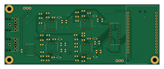
About the Wireless-Graphical-Visualizer PCB
Wireless-Graphical-Visualizer is an open source PCB design by ZIRoberts, published on GitHub. It is a 2-layer board measuring 137.8 × 53.7 mm, with 113 components from 33 distinct parts.
Other key parts include the TLV2371IP, MCP1700T-2502E_TT, TLV2372IP and MAX4617CPE+. By type, the board carries 47 resistors, 39 capacitors, 16 diodes, 8 ICs and 3 connectors.
It belongs with the iot & wireless and audio designs in this gallery.
From the project
Maintain all documents relating to the creation of the Wireless Graphical Equalizer project I started in 2021
There is a single board in this sytem and it is broken up into three sections represented by their own respeitive schematic sheet. The first section is the board's inputs. This includes the audio input, power input and regulation, and the audio isolation buffer. Audio is input by a standard 3.5 mm audio cable through one of the two linked audio jacks and enters the system by passing through the unity gain isolation buffer. The two audio jacks are to allow for the user to pass the audio through the device to a speaker without any disortion caused by the filters. Power is inputed by a standard…
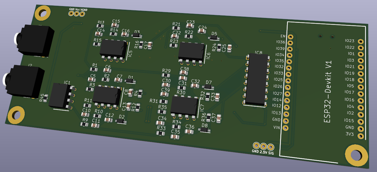
Main components on the Wireless-Graphical-Visualizer
Wireless-Graphical-Visualizer bill of materials (BOM)
113 components, 33 distinct parts — part numbers from the project's BOM.
| Qty | Part | Footprint | Refs |
|---|---|---|---|
| 1 | TLV2371IP | DIP794W53P254L959H508Q8N | IC1 |
| 2 | MCP1700T-2502E_TT | SOT95P237X112-3N | IC2, IC3 |
| 4 | TLV2372IP | DIP794W53P254L959H508Q8N | IC4, IC5, IC6, IC7 |
| 1 | MAX4617CPE+ | DIP794W56P254L1918H457Q16N | IC8 |
| 2 | SJ1-3523N | SJ13523N | J1, J2 |
| 1 | 10033526-N3212LF | 10033526N3212LF | J3 |
| 8 | BAT54W-HG3-18 | SOD3716X135N | D1, D2, D3, D4, D5, D6, D7, D8 |
| 8 | MMBD101LT1G | SOT96P237X111-3N | D9, D10, D11, D12, D13, D14, D15, D16 |
| 5 | C-USC0805 | C_0805_2012Metric_Pad1.18x1.45mm_HandSolder | C1, C2, C3, C4, C9 |
| 12 | .01u | C_0805_2012Metric_Pad1.18x1.45mm_HandSolder | C5, C6, C8, C10, C11, C13, C17, C21 +4 |
| 8 | 22u | C_0805_2012Metric_Pad1.18x1.45mm_HandSolder | C7, C12, C16, C20, C24, C28, C32, C36 |
| 4 | .02u | C_0805_2012Metric_Pad1.18x1.45mm_HandSolder | C14, C15, C18, C19 |
| 8 | .1u | C_0805_2012Metric_Pad1.18x1.45mm_HandSolder | C22, C23, C26, C27, C30, C31, C38, C39 |
| 2 | 1u | C_0805_2012Metric_Pad1.18x1.45mm_HandSolder | C34, C35 |
| 1 | 4750 | R_0805_2012Metric_Pad1.20x1.40mm_HandSolder | R1 |
| 2 | 23700 | R_0805_2012Metric_Pad1.20x1.40mm_HandSolder | R2, R22 |
| 3 | 267 | R_0805_2012Metric_Pad1.20x1.40mm_HandSolder | R3, R23, R31 |
| 8 | 100k | R_0805_2012Metric_Pad1.20x1.40mm_HandSolder | R4, R12, R16, R20, R24, R28, R32, R36 |
| 15 | R-US_R0805 | R_0805_2012Metric_Pad1.20x1.40mm_HandSolder | R5, R6, R7, R8, R37, R38, R39, R40 +7 |
| 2 | 10000 | R_0805_2012Metric_Pad1.20x1.40mm_HandSolder | R9, R17 |
Show 13 more
| Qty | Part | Footprint | Refs |
|---|---|---|---|
| 1 | 47500 | R_0805_2012Metric_Pad1.20x1.40mm_HandSolder | R10 |
| 1 | 348 | R_0805_2012Metric_Pad1.20x1.40mm_HandSolder | R11 |
| 3 | 7500 | R_0805_2012Metric_Pad1.20x1.40mm_HandSolder | R13, R25, R29 |
| 1 | 34800 | R_0805_2012Metric_Pad1.20x1.40mm_HandSolder | R14 |
| 1 | 301 | R_0805_2012Metric_Pad1.20x1.40mm_HandSolder | R15 |
| 1 | 54900 | R_0805_2012Metric_Pad1.20x1.40mm_HandSolder | R18 |
| 1 | 806 | R_0805_2012Metric_Pad1.20x1.40mm_HandSolder | R19 |
| 1 | 4990 | R_0805_2012Metric_Pad1.20x1.40mm_HandSolder | R21 |
| 1 | 40200 | R_0805_2012Metric_Pad1.20x1.40mm_HandSolder | R26 |
| 2 | 402 | R_0805_2012Metric_Pad1.20x1.40mm_HandSolder | R27, R35 |
| 1 | 35700 | R_0805_2012Metric_Pad1.20x1.40mm_HandSolder | R30 |
| 1 | 1210 | R_0805_2012Metric_Pad1.20x1.40mm_HandSolder | R33 |
| 1 | 6040 | R_0805_2012Metric_Pad1.20x1.40mm_HandSolder | R34 |
Wireless-Graphical-Visualizer design files
The KiCad project lives in the ZIRoberts/Wireless-Graphical-Visualizer repository on GitHub; these links point at the commit this page was built from.
Wireless-Graphical-Visualizer: common questions
How big is the Wireless-Graphical-Visualizer PCB?
The Wireless-Graphical-Visualizer measures 137.8 × 53.7 mm, has 2 copper layers and is 1.6 mm thick.
How many components are on the Wireless-Graphical-Visualizer?
113 components, from 33 distinct parts, with part numbers taken from the project's own BOM. The full bill of materials is listed on this page.
Where can I download the Wireless-Graphical-Visualizer design files?
From the ZIRoberts/Wireless-Graphical-Visualizer repository on GitHub, which has the KiCad layout, the schematic and the BOM; the links under Design files point to each one.
Can I use the Wireless-Graphical-Visualizer design in my own project?
The repository has no license, so all rights stay with ZIRoberts. Use it as a reference, and ask the author before reusing the design.
Similar boards

EinkPDA screen
TalismanDesign
95 × 54 mm27 parts2LApache-2.02.0k
KLOR
GEIGEIGEIST
160.2 × 118.3 mm79 parts2LGPL-3.01.2k
RPi RM0 WiFi/Bluetooth Module
schlae
11.1 × 14 mm76 parts6LNo license1.0k
ButtonsLEDs
shanteacontrols
390 × 37 mm82 parts2LApache-2.0956
Pots
390 × 93 mm75 parts2LApache-2.0956
USB
52 × 12.6 mm6 parts2LApache-2.0956