
CyberKeeb2040

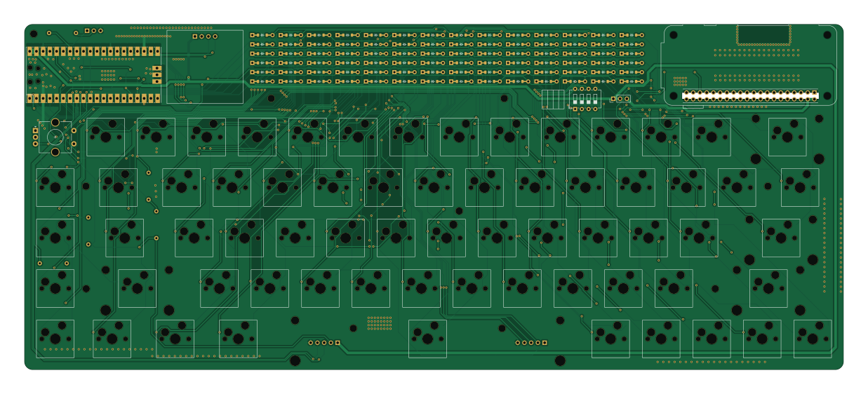
About the CyberKeeb2040 PCB
CyberKeeb2040 is an open source RP2040/RP2350 PCB design by zli117, published on GitHub under the CC-BY-SA-4.0 license. It is a 2-layer board measuring 308.8 × 130.3 mm, with 163 components from 77 distinct parts.
Its main chip is the Pico, from the RP2040/RP2350 family. By type, the board carries 84 diodes, 68 switches, 5 resistors, 4 connectors, 1 IC and 1 capacitor.
It belongs with the keyboards designs in this gallery.
From the project
Hardware design for a mechanical keyboard based on RP2040 that also has a Pi Zero onboard.
- CyberKeeb 2040 - Table of Contents - Build - PCB - Frame - Photos - V2 - V1 - Q\&A - PCB Library Licenses
Frame/MainBoard/TopBar.dxf: 3mm acrlyic Frame/MainBoard/Plate.dxf: 1.5mm acrlyic * Frame/MainBoard/Bottom.dxf: 3mm acrlyic
Special thanks to icon-oclast for asking these great questions.
The 4 positions are for each line of the SPI connection between the pi pico and pi zero. This allows cutting the connections between pi pico and pi zero without cutting the power connections. I initially designed it for the (paranoid) scenario where I can't kill the pi zero, but doesn't want it to do…
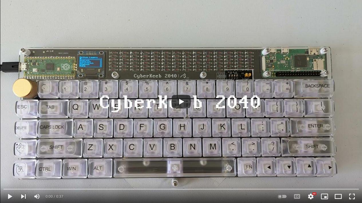
Main components on the CyberKeeb2040
CyberKeeb2040 bill of materials (BOM)
163 components, 77 distinct parts.
| Qty | Part | Footprint | Refs |
|---|---|---|---|
| 1 | Pico | RPi_Pico_SMD_TH | U1 |
| 1 | JMD0.96C | JMD0.96C | J2 |
| 1 | WS2812 | PinHeader_1x03_P2.54mm_Vertical | J3 |
| 1 | Extra_Keys | PinSocket_1x05_P2.54mm_Horizontal | J4 |
| 1 | JoyStick_Or_I2C1 | PinSocket_1x05_P2.54mm_Horizontal | J5 |
| 1 | PiPowerSwitch | PinHeader_1x03_P2.54mm_Vertical | SW1 |
| 1 | SPI_SW | SW_DIP_SPSTx04_Slide_6.7x11.72mm_W7.62mm_P2.54mm_LowProfile | SW2 |
| 1 | SW_` | SW_Hotswap_Kailh_MX_1.00u | SW4 |
| 1 | SW_1 | SW_Hotswap_Kailh_MX_1.00u | SW5 |
| 1 | SW_2 | SW_Hotswap_Kailh_MX_1.00u | SW6 |
| 1 | SW_3 | SW_Hotswap_Kailh_MX_1.00u | SW7 |
| 1 | SW_4 | SW_Hotswap_Kailh_MX_1.00u | SW8 |
| 1 | SW_5 | SW_Hotswap_Kailh_MX_1.00u | SW9 |
| 1 | SW_6 | SW_Hotswap_Kailh_MX_1.00u | SW10 |
| 1 | SW_7 | SW_Hotswap_Kailh_MX_1.00u | SW11 |
| 1 | SW_8 | SW_Hotswap_Kailh_MX_1.00u | SW12 |
| 1 | SW_9 | SW_Hotswap_Kailh_MX_1.00u | SW13 |
| 1 | SW_0 | SW_Hotswap_Kailh_MX_1.00u | SW14 |
| 1 | SW_- | SW_Hotswap_Kailh_MX_1.00u | SW15 |
| 1 | SW_+ | SW_Hotswap_Kailh_MX_1.00u | SW16 |
Show 57 more
| Qty | Part | Footprint | Refs |
|---|---|---|---|
| 1 | SW_esc | SW_Hotswap_Kailh_MX_1.00u | SW17 |
| 1 | SW_tab | SW_Hotswap_Kailh_MX_1.50u | SW18 |
| 1 | SW_q | SW_Hotswap_Kailh_MX_1.00u | SW19 |
| 1 | SW_w | SW_Hotswap_Kailh_MX_1.00u | SW20 |
| 1 | SW_e | SW_Hotswap_Kailh_MX_1.00u | SW21 |
| 1 | SW_r | SW_Hotswap_Kailh_MX_1.00u | SW22 |
| 1 | SW_t | SW_Hotswap_Kailh_MX_1.00u | SW23 |
| 1 | SW_y | SW_Hotswap_Kailh_MX_1.00u | SW24 |
| 1 | SW_u | SW_Hotswap_Kailh_MX_1.00u | SW25 |
| 1 | SW_i | SW_Hotswap_Kailh_MX_1.00u | SW26 |
| 1 | SW_o | SW_Hotswap_Kailh_MX_1.00u | SW27 |
| 1 | SW_p | SW_Hotswap_Kailh_MX_1.00u | SW28 |
| 1 | SW_[ | SW_Hotswap_Kailh_MX_1.00u | SW29 |
| 1 | SW_back | SW_Hotswap_Kailh_MX_2.00u | SW30 |
| 1 | SW_del | SW_Hotswap_Kailh_MX_1.00u | SW31 |
| 1 | SW_caps | SW_Hotswap_Kailh_MX_1.75u | SW32 |
| 1 | SW_a | SW_Hotswap_Kailh_MX_1.00u | SW33 |
| 1 | SW_s | SW_Hotswap_Kailh_MX_1.00u | SW34 |
| 1 | SW_f | SW_Hotswap_Kailh_MX_1.00u | SW35 |
| 1 | SW_g | SW_Hotswap_Kailh_MX_1.00u | SW36 |
| 1 | SW_h | SW_Hotswap_Kailh_MX_1.00u | SW37 |
| 1 | SW_j | SW_Hotswap_Kailh_MX_1.00u | SW38 |
| 1 | SW_k | SW_Hotswap_Kailh_MX_1.00u | SW39 |
| 1 | SW_l | SW_Hotswap_Kailh_MX_1.00u | SW40 |
| 1 | SW_; | SW_Hotswap_Kailh_MX_1.00u | SW41 |
| 1 | SW_' | SW_Hotswap_Kailh_MX_1.00u | SW42 |
| 1 | SW_] | SW_Hotswap_Kailh_MX_1.00u | SW43 |
| 1 | SW_ins | SW_Hotswap_Kailh_MX_1.00u | SW44 |
| 1 | SW_shift | SW_Hotswap_Kailh_MX_2.25u | SW45 |
| 1 | SW_z | SW_Hotswap_Kailh_MX_1.00u | SW46 |
| 1 | SW_x | SW_Hotswap_Kailh_MX_1.00u | SW47 |
| 1 | SW_v | SW_Hotswap_Kailh_MX_1.00u | SW48 |
| 1 | SW_b | SW_Hotswap_Kailh_MX_1.00u | SW49 |
| 1 | SW_n | SW_Hotswap_Kailh_MX_1.00u | SW50 |
| 1 | SW_m | SW_Hotswap_Kailh_MX_1.00u | SW51 |
| 1 | SW_, | SW_Hotswap_Kailh_MX_1.00u | SW52 |
| 1 | SW_. | SW_Hotswap_Kailh_MX_1.00u | SW53 |
| 1 | SW_/ | SW_Hotswap_Kailh_MX_1.00u | SW54 |
| 1 | SW_r_shift | SW_Hotswap_Kailh_MX_2.75u | SW55 |
| 1 | SW_bkslash | SW_Hotswap_Kailh_MX_1.50u | SW56 |
| 1 | SW_fn1 | SW_Hotswap_Kailh_MX_1.00u | SW57 |
| 1 | SW_ctrl | SW_Hotswap_Kailh_MX_1.25u | SW58 |
| 1 | SW_super | SW_Hotswap_Kailh_MX_1.25u | SW59 |
| 1 | SW_alt | SW_Hotswap_Kailh_MX_1.25u | SW60 |
| 1 | SW_c | SW_Hotswap_Kailh_MX_1.00u | SW61 |
| 1 | SW_d | SW_Hotswap_Kailh_MX_1.00u | SW62 |
| 1 | SW_space | SW_Hotswap_Kailh_MX_6.25u | SW63 |
| 1 | SW_fn2 | SW_Hotswap_Kailh_MX_1.00u | SW64 |
| 1 | SW_left | SW_Hotswap_Kailh_MX_1.00u | SW65 |
| 1 | SW_down | SW_Hotswap_Kailh_MX_1.00u | SW66 |
| 1 | SW_up | SW_Hotswap_Kailh_MX_1.00u | SW67 |
| 1 | SW_right | SW_Hotswap_Kailh_MX_1.00u | SW68 |
| 1 | SW_enter | SW_Hotswap_Kailh_MX_2.25u | SW69 |
| 84 | D | D_DO-35_SOD27_P7.62mm_Horizontal | D1, D2, D3, D4, D5, D6, D7, D8 +76 |
| 1 | 0.01 μF | C_1206_3216Metric_Pad1.33x1.80mm_HandSolder | C1 |
| 1 | 330 | R_Axial_DIN0207_L6.3mm_D2.5mm_P10.16mm_Horizontal_0603 | R1 |
| 4 | 10k | R_Axial_DIN0207_L6.3mm_D2.5mm_P10.16mm_Horizontal_0402 | R2, R3, R4, R5 |
CyberKeeb2040 design files
The KiCad project lives in the zli117/CyberKeeb2040 repository on GitHub; these links point at the commit this page was built from.
CyberKeeb2040: common questions
What microcontroller does the CyberKeeb2040 use?
The CyberKeeb2040 is built around the Pico, from the RP2040/RP2350 family.
How big is the CyberKeeb2040 PCB?
The CyberKeeb2040 measures 308.8 × 130.3 mm, has 2 copper layers and is 1.6 mm thick.
How many components are on the CyberKeeb2040?
163 components, from 77 distinct parts. The full bill of materials is listed on this page.
Where can I download the CyberKeeb2040 design files?
From the zli117/CyberKeeb2040 repository on GitHub, which has the KiCad layout and the schematic; the links under Design files point to each one.
Can I use the CyberKeeb2040 design in my own project?
Yes, under the terms of its CC-BY-SA-4.0 license, which zli117 chose for the repository.
Can I test firmware for the CyberKeeb2040 without the hardware?
Yes. HardLabs builds a simulation of the board from its netlist and BOM, so you can run and debug RP2040/RP2350 firmware against it before you order a PCB.
Similar boards
 RP2040/RP2350
Open Book Abridged Edition
joeycastillo
85 × 115 mm29 parts2LCC-BY-SA-4.08.1k RP2040/RP2350
Corne
foostan
277.2 × 107.5 mm164 parts2LCC-BY-4.07.7k RP2040/RP2350
Corne
277.2 × 107.5 mm164 parts2LCC-BY-4.07.7k RP2040/RP2350
LogicAnalyzer
gusmanb
57 × 55.2 mm6 parts2LGPL-3.05.0k RP2040/RP2350
Jitx design
55.5 × 65 mm26 parts4LGPL-3.05.0k RP2040/RP2350
Pro V2
kata0510
290.1 × 130 mm270 parts2LMIT2.3k