
Rp-2350-cam module

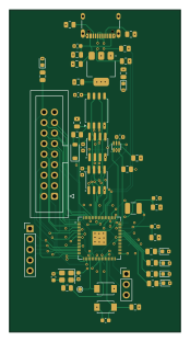
About the Rp-2350-cam module
Rp-2350-cam module is an open source RP2040/RP2350 PCB design by zolotvok, published on GitHub under the CC-BY-SA-4.0 license. It is a 4-layer board measuring 41.4 × 77.8 mm, with 67 components from 33 distinct parts.
Its main chip is the 2.2UF, from the RP2040/RP2350 family. Other key parts include the APS1604M-3SQRX-SN, W25Q128JVS, 74LVC1G19 and NCP1117-3.3_SOT223. By type, the board carries 28 capacitors, 18 resistors, 6 inductors, 5 ICs, 3 connectors and 2 crystals.
From the project
rp based camera module
Second prototype of the camera module, work in progress. It is built on proto1 and changes how the camera is attached and what the board can talk to.
The schematic has a section for each of these:
- Camera supply and clock on the board. The support circuitry of the Adafruit OV5640 breakout is moved onto the board: a 24-pin OV5640 module connector (X1), 2.8 V and 1.5 V regulators (TLV74328, TLV74315) and a 24 MHz oscillator. A solder jumper selects the camera clock: generated by the RP2350 (external XCLK, as on proto1) or taken from the oscillator (internal XCLK). Only the circuit comes from…
Main components on the Rp-2350-cam module
Rp-2350-cam module bill of materials (BOM)
67 components, 33 distinct parts — part numbers from the project's BOM.
| Qty | Part | Footprint | Refs |
|---|---|---|---|
| 2 | APS1604M-3SQRX-SN APS1604M-3SQRx-SN | SOIC-8_3.9x4.9mm_P1.27mm | U1, U7 |
| 1 | W25Q128JVS | SOIC-8_5.3x5.3mm_P1.27mm | U2 |
| 1 | 74LVC1G19 | SOT-363_SC-70-6 | U4 |
| 1 | NCP1117-3.3_SOT223 | SOT-223-3_TabPin2 | U5 |
| 1 | RP2350B | QFN-80-1EP_10x10mm_P0.4mm_EP3.4x3.4mm | X4 |
| 1 | 12MHZ_10PF_50OHM 12MHz_10pF_50ohm | Crystal_SMD_3225-4Pin_3.2x2.5mm | Y1 |
| 1 | USB_C_RECEPTACLE_USB2.0_14P USB_C_Receptacle_USB2.0_14P | USB_C_Receptacle_XKB_U262-16XN-4BVC11 | J1 |
| 1 | CONN_02X09_COUNTER_CLOCKWISE Conn_02x09_Counter_Clockwise | IDC-Header_2x09_P2.54mm_Vertical | J2 |
| 1 | CONN_01X05_PIN Conn_01x05_Pin | PinHeader_1x05_P2.54mm_Vertical | J3 |
| 1 | JST_SH3 | PinHeader_1x03_P2.54mm_Vertical | DEBUG0 |
| 2 | TS-1088-AR02016 | SW_TS-1088-AR02016 | S1, S2 |
| 1 | C2297 EMERALD GREEN | LED_0603_1608Metric | ON0 |
| 1 | 1N4148 | D_SOD-123 | D3 |
| 2 | C84256 RED | LED_0603_1608Metric | L0, L2 |
| 1 | C2046640 DFE252012F-3R3M=P2 | L_1210_3225Metric | L1 |
| 1 | C2297 EMERALD GREEN | LED_0603_1608Metric | L3 |
| 1 | C34499 YELLOW | LED_0603_1608Metric | L4 |
| 1 | C2297 BLUE | LED_0603_1608Metric | L5 |
| 2 | 2.2UF 2.2u | C_0603_1608Metric | C1, C4 |
| 7 | 1UF 1u | C_0603_1608Metric | C2, C7, C9, C11, C12, C13, C16 |
Show 13 more
| Qty | Part | Footprint | Refs |
|---|---|---|---|
| 1 | 10UF 10u | C_0805_2012Metric | C3 |
| 11 | 0.1UF 100n | C_0603_1608Metric | C5, C6, C8, C14, C17, C21, C22, C23 +3 |
| 1 | 10UF_0805 10u | C_0805_2012Metric | C10 |
| 1 | 10UF_0805 10u | C_0603_1608Metric | C15 |
| 1 | 1u | C_0603_1608Metric | C18 |
| 2 | 20P 20p | C_0603_1608Metric | C26, C27 |
| 2 | 10U 10u | C_0805_2012Metric | C34, C35 |
| 2 | 5K1 5k1 | R_0805_2012Metric | R1, R3 |
| 1 | 200 | R_0805_2012Metric | R4 |
| 1 | 10 | R_0805_2012Metric | R5 |
| 4 | 10K | R_0805_2012Metric | R6, R9, R16, R21 |
| 2 | C17561 22 | R_0805_2012Metric | R7, R8 |
| 8 | 1K | R_0805_2012Metric | R23, R24, R25, R26, R27, R28, R29, R30 |
Rp-2350-cam module design files
The KiCad project lives in the zolotvok/Rp-2350-cam-module repository on GitHub; these links point at the commit this page was built from.
Rp-2350-cam module: common questions
What microcontroller does the Rp-2350-cam module use?
The Rp-2350-cam module is built around the 2.2UF, from the RP2040/RP2350 family.
How big is the Rp-2350-cam module?
The Rp-2350-cam module measures 41.4 × 77.8 mm, has 4 copper layers and is 1.6 mm thick.
How many components are on the Rp-2350-cam module?
67 components, from 33 distinct parts, with part numbers taken from the project's own BOM. The full bill of materials is listed on this page.
Where can I download the Rp-2350-cam module design files?
From the zolotvok/Rp-2350-cam-module repository on GitHub, which has the KiCad layout, the schematic and the BOM; the links under Design files point to each one.
Can I use the Rp-2350-cam module design in my own project?
Yes, under the terms of its CC-BY-SA-4.0 license, which zolotvok chose for the repository.
Can I test firmware for the Rp-2350-cam module without the hardware?
Yes. HardLabs builds a simulation of the board from its netlist and BOM, so you can run and debug RP2040/RP2350 firmware against it before you order a PCB.
Similar boards
 RP2040/RP2350
OSO-BOOK-C1
joeycastillo
85 × 115 mm29 parts2LCC-BY-SA-4.08.1k RP2040/RP2350
Corne cherry
foostan
277.2 × 107.5 mm164 parts2LCC-BY-4.07.7k RP2040/RP2350
Corne chocolate
277.2 × 107.5 mm164 parts2LCC-BY-4.07.7k RP2040/RP2350
Jitx design
gusmanb
55.5 × 65 mm26 parts4LGPL-3.05.0k RP2040/RP2350
LogicAnalyzer
57 × 55.2 mm6 parts2LGPL-3.05.0k RP2040/RP2350
Main
google
98 × 71 mm102 parts2LApache-2.02.9k