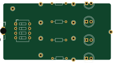
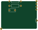
FOC INVERTER

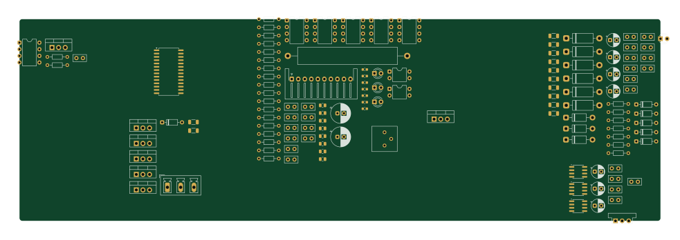
About the FOC INVERTER PCB
FOC INVERTER is an open source PCB design by Abdelrahman-Elnahrawy, published on GitHub under the GPL-3.0 license. It is a 2-layer board measuring 245.4 × 77.5 mm, with 132 components from 41 distinct parts.
Other key parts include the IR2136S, 6N137, LM7805_TO220, PC817 and ACS712xLCTR-20A. By type, the board carries 49 resistors, 42 capacitors, 14 ICs, 9 diodes, 4 LEDs and 2 connectors.
From the project
This repository serves as a portfolio and archive for my Printed Circuit Board (PCB) designs developed using KiCad. It includes everything from initial schematic capture to 3D modeling and production-ready manufacturing files.
This repository serves as a portfolio and archive for my Printed Circuit Board (PCB) designs developed using KiCad. It includes everything from initial schematic capture to 3D modeling and production-ready manufacturing files.
1. Schematic Design: Defining connections and selecting components. 2. Footprint Assignment: Linking symbols to physical footprints. 3. Board Layout: Defining board edges, placing components, and routing traces. 4. Design Rule Check (DRC): Ensuring the board meets manufacturing constraints. 5. 3D Visualization: Verifying mechanical fit and component clearances.
Main components on the FOC INVERTER
FOC INVERTER bill of materials (BOM)
132 components, 41 distinct parts — part numbers from the project's BOM.
| Qty | Part | Footprint | Refs |
|---|---|---|---|
| 1 | IR2136S | SOIC-28W_7.5x17.9mm_P1.27mm | U1 |
| 6 | 6N137 | DIP-8_W7.62mm | U2, U4, U5, U6, U7, U8 |
| 1 | LM7805_TO220 | TO-220-3_Vertical | U3 |
| 2 | PC817 | DIP-4_W7.62mm | U9, U10 |
| 3 | ACS712xLCTR-20A | SOIC-8_3.9x4.9mm_P1.27mm | U11, U12, U13 |
| 1 | MIC5219-3.3YM5 | Converter_DCDC_Murata_OKI-78SR_Vertical | U15 |
| 1 | CONN_01X10_PIN Conn_01x10_Pin | JST_XH_S10B-XH-A-1_1x10_P2.50mm_Horizontal | J1 |
| 1 | CONN_01X03_PIN Conn_01x03_Pin | PhoenixContact_MCV_1,5_3-G-5.08_1x03_P5.08mm_Vertical | J2 |
| 6 | STP20NM60FP | TO-220-3_Vertical | STP20NM60FP1, STP20NM60FP2, STP20NM60FP3, STP20NM60FP4, STP20NM60FP5, STP20NM60FP6 |
| 6 | P6KE18CA | D_DO-15_P12.70mm_Horizontal | TVS1, TVS2, TVS3, TVS4, TVS5, TVS6 |
| 1 | BLUE - 3MM | LED_D3.0mm_IRBlack | EN1 |
| 1 | RED - 3MM | LED_D3.0mm_IRBlack | FAULT1 |
| 1 | yellow - 3MM | LED_D3.0mm_IRBlack | VCC_5V1 |
| 1 | GREEN - 3MM | LED_D3.0mm_IRBlack | VCC_15 |
| 6 | 1N4148 | D_DO-35_SOD27_P7.62mm_Horizontal | D1, D2, D3, D4, D5, D6 |
| 3 | UF4007 | D_DO-41_SOD81_P10.16mm_Horizontal | D7, D8, D9 |
| 13 | 100NF 100nF | C_Disc_D5.0mm_W2.5mm_P2.50mm | C1, C2, C4, C5, C6, C7, C8, C17 +5 |
| 1 | C | C_Disc_D5.0mm_W2.5mm_P2.50mm | C3 |
| 2 | 100UF 100uF | CP_Radial_D7.5mm_P2.50mm | C9, C10 |
| 6 | 100PF 100pF | C_0603_1608Metric | C11, C12, C13, C14, C15, C16 |
Show 21 more
| Qty | Part | Footprint | Refs |
|---|---|---|---|
| 1 | 470PF 470pF | C_0603_1608Metric | C19 |
| 1 | 200NF 200nF | C_Disc_D5.0mm_W2.5mm_P2.50mm | C20 |
| 6 | 1NF 1nF | C_Disc_D5.0mm_W2.5mm_P2.50mm | C21, C22, C23, C24, C25, C26 |
| 4 | 10UF 10uF | CP_Radial_D5.0mm_P2.50mm | C28, C30, C32, C34 |
| 3 | 100nF | C_Disc_D5.0mm_W2.5mm_P2.50mm | C35, C37, C39 |
| 3 | 1uF | CP_Radial_D5.0mm_P2.50mm | C36, C38, C40 |
| 1 | 2.2uF | C_Disc_D5.0mm_W2.5mm_P2.50mm | C41 |
| 1 | 470pF | C_Disc_D5.0mm_W2.5mm_P2.50mm | C43 |
| 9 | 1K | R_Axial_DIN0204_L3.6mm_D1.6mm_P7.62mm_Horizontal | R1, R2_T1, R4, R6, R8, R10, R12, R20 +1 |
| 1 | 10k Ω | Potentiometer_Bourns_3386P_Vertical | R1_T1 |
| 5 | 200 | R_Axial_DIN0204_L3.6mm_D1.6mm_P7.62mm_Horizontal | R2, R3, R9, R11, R19 |
| 2 | 200 | R_Axial_DIN0204_L3.6mm_D1.6mm_P7.62mm_Horizontal | R5, R7 |
| 6 | 200 | R_0805_2012Metric | R13, R14, R15, R16, R17, R18 |
| 1 | 1.3K | R_Axial_DIN0204_L3.6mm_D1.6mm_P7.62mm_Horizontal | R21 |
| 4 | 3KΩ | R_Axial_DIN0204_L3.6mm_D1.6mm_P7.62mm_Horizontal | R23, R24, R25, R47 |
| 1 | 0.11 Ω | R_Axial_Power_L38.0mm_W6.4mm_P45.72mm | R26 |
| 1 | 1kΩ | R_0805_2012Metric | R27 |
| 1 | 200KΩ | R_0805_2012Metric | R28 |
| 6 | 10Ω | R_1206_3216Metric | R29, R31, R33, R35, R36, R37 |
| 6 | 17Ω | R_1206_3216Metric | R30, R32, R34, R38, R39, R40 |
| 6 | 22Ω | R_Axial_DIN0204_L3.6mm_D1.6mm_P7.62mm_Horizontal | R41, R42, R43, R44, R45, R46 |
FOC INVERTER design files
The KiCad project lives in the Abdelrahman-Elnahrawy/KiCad repository on GitHub; these links point at the commit this page was built from.
FOC INVERTER: common questions
How big is the FOC INVERTER PCB?
The FOC INVERTER measures 245.4 × 77.5 mm, has 2 copper layers and is 1.6 mm thick.
How many components are on the FOC INVERTER?
132 components, from 41 distinct parts, with part numbers taken from the project's own BOM. The full bill of materials is listed on this page.
Where can I download the FOC INVERTER design files?
From the Abdelrahman-Elnahrawy/KiCad repository on GitHub, which has the KiCad layout, the schematic and the BOM; the links under Design files point to each one.
Can I use the FOC INVERTER design in my own project?
Yes, under the terms of its GPL-3.0 license, which Abdelrahman-Elnahrawy chose for the repository.