
Bipolar--5-V-to-0-3.3-V-Sensor-Interface-Board

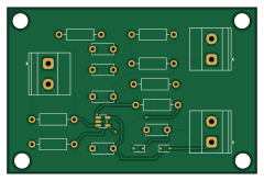
About the Bipolar--5-V-to-0-3.3-V-Sensor-Interface-Board
Bipolar--5-V-to-0-3.3-V-Sensor-Interface-Board is an open source PCB design by abdurrahman-eee, published on GitHub. It is a 2-layer board measuring 60 × 40 mm, with 18 components from 11 distinct parts.
Other key parts include the TLV9061xDBV. By type, the board carries 7 resistors, 5 capacitors, 2 diodes and 1 IC.
It belongs with the sensors and power & battery designs in this gallery.
From the project
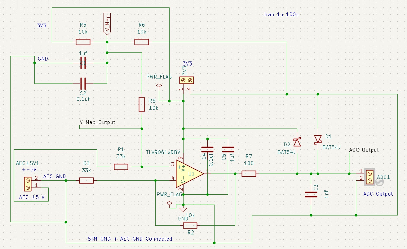
The Bipolar ±5 V to 0-3.3 V Sensor Interface Board is a general-purpose analog front-end designed to safely connect bipolar ±5 V sensor outputs to 3.3 V microcontroller ADC inputs. Many industrial and laboratory sensors produce bipolar signals, while modern microcontrollers can only measure unipolar, low-voltage signals.
A professional-grade analog signal conditioning circuit designed to interface bipolar ±5V analog signals with precision microcontroller ADC inputs (0-3.3V). This project provides a complete hardware solution including schematic design, PCB layout, and simulation verification using low-power operational amplifiers.
Key Specifications: - Input Signal: ±5V bipolar (10VPP peak-to-peak) - Output Range: 0-3.3V unipolar (3-bit equivalent @ 410mV/step) - Topology: Non-inverting scaling amplifier with DC offset - Op-Amp: Texas Instruments TLV9061/TLV9062 (Low Power, Rail-to-Rail) - Supply Voltage…
Main components on the Bipolar--5-V-to-0-3.3-V-Sensor-Interface-Board
Bipolar--5-V-to-0-3.3-V-Sensor-Interface-Board bill of materials (BOM)
18 components, 11 distinct parts.
| Qty | Part | Footprint | Refs |
|---|---|---|---|
| 1 | TLV9061xDBV | SOT-23-5 | U1 |
| 1 | 3.3 | TerminalBlock_Phoenix_MKDS-1,5-2_1x02_P5.00mm_Horizontal | 3V3 |
| 1 | Screw_Terminal_01x02 | TerminalBlock_Phoenix_MKDS-1,5-2_1x02_P5.00mm_Horizontal | ADC1 |
| 1 | 5 | TerminalBlock_Phoenix_MKDS-1,5-2_1x02_P5.00mm_Horizontal | AEC±5V1 |
| 2 | BAT54J | D_SOD-323F | D1, D2 |
| 2 | 0.1uf | C_Disc_D5.0mm_W2.5mm_P5.00mm | C1, C4 |
| 2 | 1uf | C_Disc_D5.0mm_W2.5mm_P5.00mm | C2, C5 |
| 1 | 1nf | C_Disc_D5.0mm_W2.5mm_P5.00mm | C3 |
| 2 | 33k | R_Axial_DIN0207_L6.3mm_D2.5mm_P10.16mm_Horizontal | R1, R3 |
| 4 | 10k | R_Axial_DIN0207_L6.3mm_D2.5mm_P10.16mm_Horizontal | R2, R5, R6, R8 |
| 1 | 100 | R_Axial_DIN0207_L6.3mm_D2.5mm_P10.16mm_Horizontal | R7 |
Bipolar--5-V-to-0-3.3-V-Sensor-Interface-Board design files
The KiCad project lives in the abdurrahman-eee/Bipolar--5-V-to-0-3.3-V-Sensor-Interface-Board repository on GitHub; these links point at the commit this page was built from.
Bipolar--5-V-to-0-3.3-V-Sensor-Interface-Board: common questions
How big is the Bipolar--5-V-to-0-3.3-V-Sensor-Interface-Board?
The Bipolar--5-V-to-0-3.3-V-Sensor-Interface-Board measures 60 × 40 mm, has 2 copper layers and is 1.6 mm thick.
How many components are on the Bipolar--5-V-to-0-3.3-V-Sensor-Interface-Board?
18 components, from 11 distinct parts. The full bill of materials is listed on this page.
Where can I download the Bipolar--5-V-to-0-3.3-V-Sensor-Interface-Board design files?
From the abdurrahman-eee/Bipolar--5-V-to-0-3.3-V-Sensor-Interface-Board repository on GitHub, which has the KiCad layout and the schematic; the links under Design files point to each one.
Can I use the Bipolar--5-V-to-0-3.3-V-Sensor-Interface-Board design in my own project?
The repository has no license, so all rights stay with abdurrahman-eee. Use it as a reference, and ask the author before reusing the design.
Similar boards

Sensor smd
scottbez1
40 × 20 mm5 parts2LApache-2.04.2k
Sensors
StuckAtPrototype
15.2 × 9 mm14 parts4LApache-2.03.8k
Stack chan
stack-chan
50 × 50 mm33 parts2LApache-2.01.7k
Display Carrier
AxxAxx
35.6 × 58.2 mm5 parts2LGPL-3.01.7k
Microphone
Mentra-Community
5.5 × 6.1 mm6 parts2LMIT1.2k
TemperaturePCB PANEL
stuartpittaway
116 × 75.5 mm178 parts2LCC-BY-NC-4.01.1k