
SiC-Based-Bi-Directional-Circuit breaker

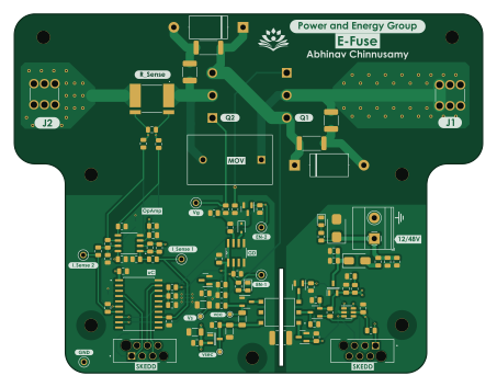
About the SiC-Based-Bi-Directional-Circuit breaker PCB
SiC-Based-Bi-Directional-Circuit breaker is an open source PIC PCB design by abhinav937, published on GitHub. It is a 2-layer board measuring 113 × 86.7 mm, with 100 components from 46 distinct parts.
Its main chip is the PIC16F15345T-E/SSVAO, from the PIC family. Other key parts include the MCP1792T-5002H/CB, PIC10F322-IOT, MCP6022 and TC4432VOA. By type, the board carries 35 resistors, 30 capacitors, 9 diodes, 6 ICs, 6 transistors and 6 test points.
It belongs with the power & battery designs in this gallery.
From the project
KiCad 7 PCB design files for E_Fuse
Main components on the SiC-Based-Bi-Directional-Circuit breaker
SiC-Based-Bi-Directional-Circuit breaker bill of materials (BOM)
100 components, 46 distinct parts — part numbers from the project's BOM.
| Qty | Part | Footprint | Refs |
|---|---|---|---|
| 1 | PIC16F15345T-E/SSVAO PIC16F15345-I/SO | SOIC127P1030X265-20N | IC2 |
| 2 | MCP1792T-5002H/CB MCP1792T-5002H_CB | SOT95P255X145-3N | IC4, IC5 |
| 1 | PIC10F322-IOT | SOT-23-6 | U1 |
| 1 | MCP6022 | SOIC127P599X175-8N | U2 |
| 1 | TC4432VOA | SOIC127P600X175-8N | U4 |
| 2 | IMW120R014M1H | IMW120R014M1H | Q1, Q2 |
| 3 | 2N7002BK,215 | SOT-23 | Q3, Q5, Q6 |
| 1 | SI2333DS Si2333DS | SOT-23-3 | Q4 |
| 1 | 7461057 Input | 7461057 | J1 |
| 1 | 7461057 Output | 7461057 | J2 |
| 1 | 12V/48V supply | TerminalBlock_Phoenix_MKDS-1,5-2_1x02_P5.00mm_Horizontal | J3 |
| 2 | 490107670612 | WURTH_490107670612 | J5, J6 |
| 1 | Varistor | VARRB750W100L2050T1200H2800 | RV1 |
| 1 | 760390014 | 760390015 | T1 |
| 1 | 10K 10k | C_0603_1608Metric | TH100 |
| 5 | 5001 | KEYSTONE_5001 | TP1, TP2, TP6, TP7, TP9 |
| 1 | 5001 5001/TestPoint | KEYSTONE_5001 | TP5 |
| 1 | BAS70-04 | SOT-23-3 | D1 |
| 2 | LED | LED_0805_2012Metric | D2, D6 |
| 1 | SM6T39A SM6T68CA | D_SMB | D3 |
Show 26 more
| Qty | Part | Footprint | Refs |
|---|---|---|---|
| 1 | US1G | D_SMA | D4 |
| 1 | BZX84C6V8 | SOT-23 | D5 |
| 1 | BZX384-B22,115 | D_SOD-323 | D7 |
| 2 | D | D_DO-201AE_P12.70mm_Horizontal | D8, D9 |
| 1 | 100NF 100nF | C_0805_2012Metric | C1 |
| 2 | 4.7NF 4.7nF | C_1812_4532Metric | C2, C16 |
| 10 | 0.1UF 0.1uF | C_0805_2012Metric | C3, C6, C17, C20, C21, C25, C26, C27 +2 |
| 2 | 10UF 10uF | C_1206_3216Metric | C4, C5 |
| 1 | 1UF 1uF | C_0805_2012Metric | C7 |
| 1 | 4700PF 4700pF | C_1812_4532Metric | C8 |
| 3 | 100PF 100pF | C_0805_2012Metric | C9, C12, C15 |
| 5 | 10000PF 10000pF | C_0805_2012Metric | C10, C11, C13, C14, C18 |
| 2 | 10UF 10uF | C_0805_2012Metric | C19, C23 |
| 1 | 4.7UF 4.7uF | C_0805_2012Metric | C22 |
| 2 | 4.7UF 4.7uF | C_1206_3216Metric | C24, C29 |
| 3 | 20R | R_0805_2012Metric | R1, R2, R32 |
| 1 | WSLP40261L000FEA | WSLP40261L000FEA | R3 |
| 7 | 100K 100k | R_0805_2012Metric | R4, R6, R7, R13, R30, R31, R35 |
| 7 | 10K | R_0805_2012Metric | R5, R8, R9, R11, R18, R25, R34 |
| 2 | 4.7K 4.7k | R_0805_2012Metric | R10, R12 |
| 7 | 20K 20k | R_0805_2012Metric | R14, R15, R19, R20, R22, R24, R33 |
| 2 | 1k | R_0805_2012Metric | R16, R17 |
| 2 | 100R | R_0805_2012Metric | R21, R23 |
| 2 | 18R | R_2512_6332Metric | R26, R27 |
| 1 | 0R | R_0805_2012Metric | R28 |
| 1 | 4.7R | R_0805_2012Metric | R29 |
SiC-Based-Bi-Directional-Circuit breaker design files
The KiCad project lives in the abhinav937/SiC-Based-Bi-Directional-Circuit-breaker repository on GitHub; these links point at the commit this page was built from.
SiC-Based-Bi-Directional-Circuit breaker: common questions
What microcontroller does the SiC-Based-Bi-Directional-Circuit breaker use?
The SiC-Based-Bi-Directional-Circuit breaker is built around the PIC16F15345T-E/SSVAO, from the PIC family.
How big is the SiC-Based-Bi-Directional-Circuit breaker PCB?
The SiC-Based-Bi-Directional-Circuit breaker measures 113 × 86.7 mm, has 2 copper layers and is 1.6 mm thick.
How many components are on the SiC-Based-Bi-Directional-Circuit breaker?
100 components, from 46 distinct parts, with part numbers taken from the project's own BOM. The full bill of materials is listed on this page.
Where can I download the SiC-Based-Bi-Directional-Circuit breaker design files?
From the abhinav937/SiC-Based-Bi-Directional-Circuit-breaker repository on GitHub, which has the KiCad layout, the schematic and the BOM; the links under Design files point to each one.
Can I use the SiC-Based-Bi-Directional-Circuit breaker design in my own project?
The repository has no license, so all rights stay with abhinav937. Use it as a reference, and ask the author before reusing the design.
Can I test firmware for the SiC-Based-Bi-Directional-Circuit breaker without the hardware?
Yes. HardLabs builds a simulation of the board from its netlist and BOM, so you can run and debug PIC firmware against it before you order a PCB.
Similar boards
 PIC
Pslab hardware
fossasia
99 × 53.3 mm187 parts4LApache-2.01.7k PIC
Lens
ervanalb
80 × 80 mm53 parts4LNo license515 PIC
Micro 8088
skiselev
152.4 × 101.6 mm71 partsGPL-3.0414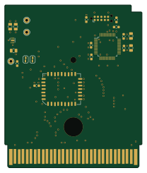 PIC
GB-CART256K-A
Gekkio
51.4 × 61 mm17 parts2LCC-BY-4.0379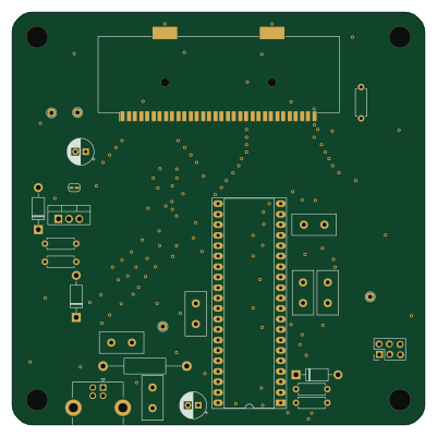 PIC
GB-CARTPP-DIY
100 × 100 mm22 parts2LCC-BY-4.0379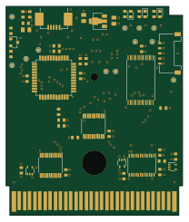 PIC
GB-LIVE32
51.4 × 61 mm46 parts4LCC-BY-4.0379