
3 open source boards using the PIC10F322-IOT
Real designs built with the PIC10F322-IOT, from public GitHub projects: a quick way to see how others power, decouple and connect it. Each board comes with its KiCad files, full parts list and a render — and you can simulate its firmware on HardLabs.
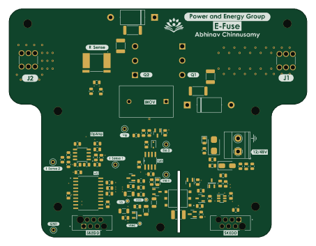 PIC
SiC-Based-Bi-Directional-Circuit breaker
abhinav937
113 × 86.7 mm100 parts2LNo license2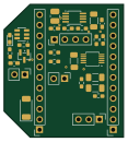 PIC
VolvocineWithCurrentSensorV4
KuraLab
29 × 32.3 mm29 parts2LNo license0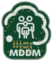 PIC
Mddm badge
polaracep
26.8 × 31.4 mm20 parts2LAGPL-3.08
The PIC10F322-IOT in open source designs
The gallery holds 3 open source boards using the PIC10F322-IOT from 3 GitHub repositories; a typical one measures about 29 × 32.3 mm and carries around 29 components.
100% are two-layer designs, the rest use four layers or more, and 33% carry an open source license.
The most starred is Mddm badge by polaracep.
Microcontrollers on boards using the PIC10F322-IOT
What boards using the PIC10F322-IOT are built for
PIC10F322-IOT: common questions
Where can I find a PIC10F322-IOT reference design?
Each of the 3 boards on this page is a real design using the PIC10F322-IOT. Open one to see how it is wired up, with the full BOM, a render of the layout and links to its KiCad files.
Which microcontrollers do boards using the PIC10F322-IOT use?
Most are built on PIC (3).
How big is a typical board using the PIC10F322-IOT?
The median is 29 × 32.3 mm, and 100% are two-layer designs.
What is the most popular open source board using the PIC10F322-IOT?
By GitHub stars, Mddm badge by polaracep, with 8 stars.
Can I simulate one of these boards using the PIC10F322-IOT before building it?
Yes. HardLabs turns a board's netlist and BOM into a working simulation, so you can boot and test firmware against it with no hardware on your desk.