
Airtap

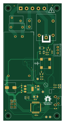
About the Airtap PCB
Airtap is an open source AVR/Arduino PCB design by ajkumar-1907, published on GitHub under the MIT license. It is a 2-layer board measuring 50 × 100 mm, with 44 components from 29 distinct parts.
Its main chip is the ATmega328-A, from the AVR/Arduino family. Other key parts include the VL53L0CXV0DH1 and AMS1117-3.3. By type, the board carries 14 resistors, 11 capacitors, 4 diodes, 3 ICs, 3 connectors and 2 transistors.
It belongs with the power & battery designs in this gallery.
From the project
Open-source library of power electronics converter topologies — KiCad schematics, working principles, use cases, and design notes for DC-DC, AC-DC, DC-AC, and AC-AC converters. Free to use, modify, and build on.
A touchless, proximity-triggered relay controller for 220 V AC loads. Hold your hand 10–30 mm above the sensing area and a VL53L0X time-of-flight sensor detects it. The ATmega328 then toggles an onboard relay to switch a lamp, fan or other mains appliance, with no physical contact.
1. Power: mains enters on J1 (LINE / NEUTRAL) through fuse F1 (0.5 A). MOV RV1 (10D561K) clamps surges, and the HLK-5M05 isolated module produces 5 V. The AMS1117 then makes 3.3 V for the ATmega328 and the VL53L0X. 2. Sensing: the VL53L0X sends out infrared laser pulses and measures their time of flight. The…
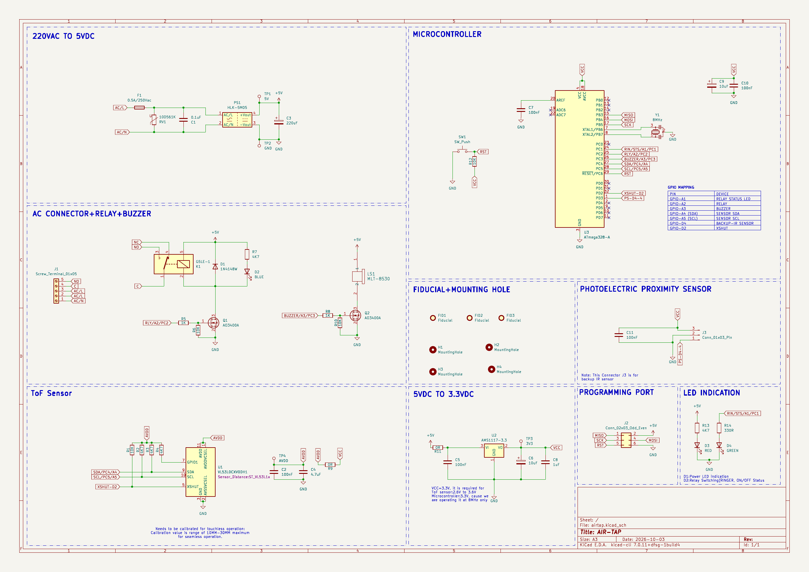
Main components on the Airtap
Airtap bill of materials (BOM)
44 components, 29 distinct parts.
| Qty | Part | Footprint | Refs |
|---|---|---|---|
| 1 | VL53L0CXV0DH1 | ST_VL53L1x | U1 |
| 1 | AMS1117-3.3 | SOT-223-3_TabPin2 | U2 |
| 1 | ATmega328-A | TQFP-32_7x7mm_P0.8mm | U3 |
| 2 | AO3400A | SOT-23 | Q1, Q2 |
| 1 | 8MHz | Resonator_SMD_Murata_CSTxExxV-3Pin_3.0x1.1mm | Y1 |
| 1 | Screw_Terminal_01x05 | TerminalBlock_bornier-5_P5.08mm | J1 |
| 1 | Conn_02x03_Odd_Even | PinHeader_2x03_P2.54mm_Vertical | J2 |
| 1 | B3B-XH-A Conn_01x03_Pin | JST_XH_B3B-XH-A_1x03_P2.50mm_Vertical | J3 |
| 1 | 0.5A/250Vac | Fuse_Littelfuse_395Series | F1 |
| 1 | G5LE-1 | Relay_SPDT_Omron-G5LE-1 | K1 |
| 1 | MLT-8530 | MLT-8530_JHE | LS1 |
| 1 | HLK-5M05 | Converter_ACDC_Hi-Link_HLK-5Mxx | PS1 |
| 1 | 10D561K | RV_Disc_D12mm_W5.8mm_P7.5mm | RV1 |
| 1 | SW_Push | SW_Tactile_SKHH_Angled | SW1 |
| 1 | 1N4148W | D_SOD-123 | D1 |
| 1 | BLUE | LED_0603_1608Metric | D2 |
| 1 | RED | LED_0603_1608Metric | D3 |
| 1 | GREEN | LED_0603_1608Metric | D4 |
| 1 | 0.1uF | C_Rect_L13.0mm_W6.0mm_P10.00mm_FKS3_FKP3_MKS4 | C1 |
| 5 | 100nF | C_0603_1608Metric | C2, C5, C7, C10, C11 |
Show 9 more
| Qty | Part | Footprint | Refs |
|---|---|---|---|
| 1 | 220uF | CP_Elec_8x10 | C3 |
| 1 | 4.7uF | C_0603_1608Metric | C4 |
| 2 | 10uF | CP_EIA-3216-18_Kemet-A | C6, C9 |
| 1 | 1uF | C_0603_1608Metric | C8 |
| 4 | 10K | R_0603_1608Metric | R1, R6, R10, R12 |
| 5 | 4K7 | R_0603_1608Metric | R2, R3, R4, R7, R13 |
| 2 | 1K | R_0603_1608Metric | R5, R8 |
| 2 | 0R | R_0603_1608Metric | R9, R11 |
| 1 | 330R | R_0603_1608Metric | R14 |
Airtap design files
The KiCad project lives in the ajkumar-1907/POWER-ELECTRONICS-LIB repository on GitHub; these links point at the commit this page was built from.
- Layoutairtap/airtap.kicad_pcb
- Schematicairtap/airtap.kicad_sch
Airtap: common questions
What microcontroller does the Airtap use?
The Airtap is built around the ATmega328-A, from the AVR/Arduino family.
How big is the Airtap PCB?
The Airtap measures 50 × 100 mm, has 2 copper layers and is 1.6 mm thick.
How many components are on the Airtap?
44 components, from 29 distinct parts. The full bill of materials is listed on this page.
Where can I download the Airtap design files?
From the ajkumar-1907/POWER-ELECTRONICS-LIB repository on GitHub, which has the KiCad layout and the schematic; the links under Design files point to each one.
Can I use the Airtap design in my own project?
Yes, under the terms of its MIT license, which ajkumar-1907 chose for the repository.
Can I test firmware for the Airtap without the hardware?
Yes. HardLabs builds a simulation of the board from its netlist and BOM, so you can run and debug AVR/Arduino firmware against it before you order a PCB.
More boards in POWER-ELECTRONICS-LIB
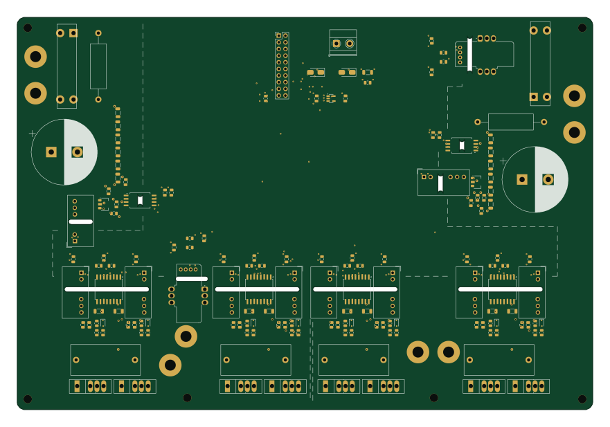
DAB 3k3W - 3.3 kW Dual Active Bridge power board
220 × 150 mm160 parts4LMIT0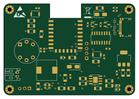 ESP8266
Air quality monitor
68 × 47.4 mm52 parts2LMIT0
Usb to uart converter
31 × 15 mm19 parts2LMIT0
Transformerless power supply
48.8 × 37.5 mm18 parts2LMIT0
Dc motor speed controller
56.5 × 29 mm15 parts2LMIT0
Boost converter
45 × 20 mm13 parts2LMIT0
Servo tester
30.5 × 27.8 mm10 parts2LMIT0
Buck converter
53 × 36 mm7 parts2LMIT0
Similar boards
 AVR/Arduino
Redox keyboard
mattdibi
162.2 × 126.5 mm77 parts2LMIT2.0k AVR/Arduino
ModuleV450
stuartpittaway
30 × 61.4 mm39 parts2LCC-BY-NC-4.01.1k AVR/Arduino
V4
30 × 50 mm38 parts2LCC-BY-NC-4.01.1k AVR/Arduino
Discipline
coseyfannitutti
304.9 × 122.8 mm170 parts2LCC-BY-NC-4.01.0k AVR/Arduino
Megadesk
gcormier
41.7 × 32.2 mm23 parts2LGPL-3.0818 AVR/Arduino
Easyduino Atmega Nano
Hanqaqa
43.4 × 18 mm30 parts4LCERN-OHL-P-2.0746