
ProjectFreeCad

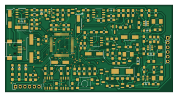
About the ProjectFreeCad PCB
ProjectFreeCad is an open source PIC PCB design by ananevego, published on GitHub. It is a 2-layer board measuring 90.8 × 47 mm, with 122 components from 50 distinct parts.
Its main chip is the PIC24FJ256GB106, from the PIC family. Other key parts include the MCP1727, LTC4411, MAX893L, MCP1525 and 74LVC1T45. By type, the board carries 51 resistors, 33 capacitors, 11 ICs, 10 diodes, 8 transistors and 3 connectors.
From the project
Конвертер библиотечных footprint-файлов KiCad .kicadmod в самостоятельные библиотеки FreePCB2 .fpl`. Написан на Python 3.10+, внешние зависимости не нужны.
Конвертер библиотечных footprint-файлов KiCad .kicadmod в самостоятельные библиотеки FreePCB2 .fpl`. Написан на Python 3.10+, внешние зависимости не нужны.
Статус: разработка продолжается. R08052012Metric, PinHeader PTH, MountingHole NPTH, SOT-23 и численные регрессии проверены автоматически. Загрузка/сохранение в FreePCB2 2.428 и физическое совмещение STL в OpenSCAD ещё требуют отдельной Windows-валидации. Есть также синтетический контроль заполненных окружностей на обоих silk-слоях. Добавлены legacy-дуги KiCad и контроль HC49-U (явно 2D), аудит текстов, DSOD-123, пакетный CLI, исходный…
Main components on the ProjectFreeCad
ProjectFreeCad bill of materials (BOM)
122 components, 50 distinct parts — part numbers from the project's BOM.
| Qty | Part | Footprint | Refs |
|---|---|---|---|
| 1 | MCP1727 | SOIC-8_3.9x4.9mm_Pitch1.27mm | U1 |
| 1 | LTC4411 | SOT-23-5 | U2 |
| 1 | PIC24FJ256GB106 | TQFP-64_10x10mm_Pitch0.5mm | U3 |
| 1 | MAX893L | SOIC-8_3.9x4.9mm_Pitch1.27mm | U4 |
| 1 | MCP1525 | SOT-23_Handsoldering | U5 |
| 3 | 74LVC1T45 | SOT-23-6 | U6, U7, U8 |
| 1 | MCP601_8PIN | SOIC-8_3.9x4.9mm_Pitch1.27mm | U9 |
| 1 | 25LC256 | SOIC-8_3.9x4.9mm_Pitch1.27mm | U10 |
| 1 | SST25VF040B | SOIC-8_3.9x4.9mm_Pitch1.27mm | U11 |
| 5 | MMBT3904 | SOT-23_Handsoldering | Q1, Q2, Q5, Q6, Q8 |
| 2 | MMBT3906 | SOT-23_Handsoldering | Q3, Q7 |
| 1 | PMV48XP | SOT-23_Handsoldering | Q4 |
| 1 | 12MHZ 12MHz | Crystal_HC49-SD_SMD | Y1 |
| 2 | CONN_01X06 | Pin_Header_Straight_1x06 | P1, P3 |
| 1 | USB_OTG | USB_Mini-B | P2 |
| 1 | SW_PUSH | SW_SPST_PTS645 | SW1 |
| 3 | 50MA 50mA | R_1210_HandSoldering | VR1, VR2, VR3 |
| 1 | MBR0520L | SOD-123 | D1 |
| 1 | YELLOW | LED-0805 | D2 |
| 1 | ORANGE | LED-0805 | D3 |
Show 30 more
| Qty | Part | Footprint | Refs |
|---|---|---|---|
| 1 | RED | LED-0805 | D4 |
| 1 | GREEN | LED-0805 | D5 |
| 1 | PMEG3020 | SOD-123 | D6 |
| 3 | 5V | SOD-123 | D7, D8, D9 |
| 1 | BAT54 | SOD-123 | D10 |
| 1 | 680UH 680uH | R_1210_HandSoldering | L1 |
| 2 | 2U2 2u2 | TantalC_SizeC_EIA-6032_HandSoldering | C1, C17 |
| 20 | 100N 100n | C_0805_HandSoldering | C2, C4, C5, C10, C11, C12, C15, C18 +12 |
| 2 | 1u | C_0805_HandSoldering | C3, C14 |
| 1 | 4U7 4u7 | C_0805_HandSoldering | C6 |
| 1 | 10N 10n | C_0805_HandSoldering | C7 |
| 3 | 10UF 10uF | TantalC_SizeC_EIA-6032_HandSoldering | C8, C26, C29 |
| 1 | 2U2 2u2 | TantalC_SizeB_EIA-3528_HandSoldering | C9 |
| 2 | 22P 22p | C_0805_HandSoldering | C13, C16 |
| 1 | 47UF 47uF | TantalC_SizeD_EIA-7343_HandSoldering | C31 |
| 6 | 1k | R_0805_HandSoldering | R1, R26, R39, R40, R41, R42 |
| 16 | 10K | R_0805_HandSoldering | R2, R3, R9, R15, R17, R23, R24, R31 +8 |
| 6 | 330 | R_0805_HandSoldering | R4, R11, R18, R19, R20, R21 |
| 1 | 200K | R_0805_HandSoldering | R5 |
| 1 | 33 | R_0805_HandSoldering | R6 |
| 2 | 2k 1% | R_0805_HandSoldering | R7, R8 |
| 3 | 2K2 2k2 | R_0805_HandSoldering | R10, R22, R46 |
| 3 | 470 | R_0805_HandSoldering | R12, R13, R14 |
| 1 | 27K | R_0805_HandSoldering | R16 |
| 1 | 3K9 | R_0805_HandSoldering | R25 |
| 1 | 47K | R_0805_HandSoldering | R27 |
| 5 | 100 | R_0805_HandSoldering | R28, R29, R30, R32, R51 |
| 3 | 4K7 | R_0805_HandSoldering | R33, R34, R35 |
| 1 | 2K7 | R_0805_HandSoldering | R36 |
| 1 | 100K | R_0805_HandSoldering | R49 |
ProjectFreeCad design files
The KiCad project lives in the ananevego/ProjectFreeCad repository on GitHub; these links point at the commit this page was built from.
ProjectFreeCad: common questions
What microcontroller does the ProjectFreeCad use?
The ProjectFreeCad is built around the PIC24FJ256GB106, from the PIC family.
How big is the ProjectFreeCad PCB?
The ProjectFreeCad measures 90.8 × 47 mm, has 2 copper layers and is 1.6 mm thick.
How many components are on the ProjectFreeCad?
122 components, from 50 distinct parts, with part numbers taken from the project's own BOM. The full bill of materials is listed on this page.
Where can I download the ProjectFreeCad design files?
From the ananevego/ProjectFreeCad repository on GitHub, which has the KiCad layout and the BOM; the links under Design files point to each one.
Can I use the ProjectFreeCad design in my own project?
The repository has no license, so all rights stay with ananevego. Use it as a reference, and ask the author before reusing the design.
Can I test firmware for the ProjectFreeCad without the hardware?
Yes. HardLabs builds a simulation of the board from its netlist and BOM, so you can run and debug PIC firmware against it before you order a PCB.
Similar boards
 PIC
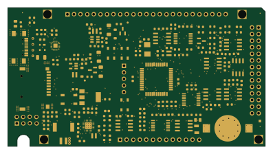
Pslab hardware
fossasia
99 × 53.3 mm187 parts4LApache-2.01.7k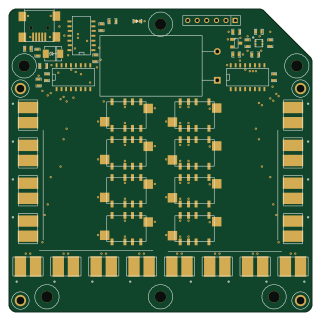 PIC
Lens
ervanalb
80 × 80 mm53 parts4LNo license515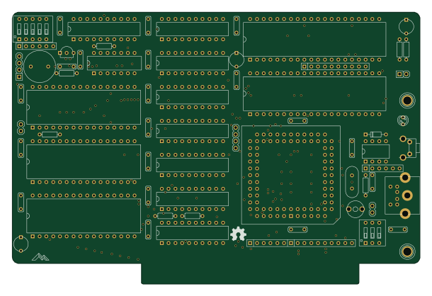 PIC
Micro 8088
skiselev
152.4 × 101.6 mm71 partsGPL-3.0414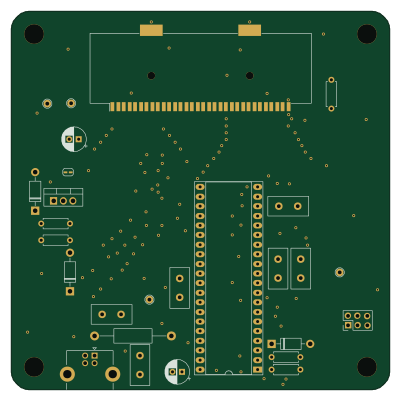 PIC
GB-CARTPP-DIY
Gekkio
100 × 100 mm22 parts2LCC-BY-4.0379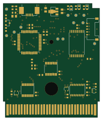 PIC
GB-LIVE32
51.4 × 61 mm46 parts4LCC-BY-4.0379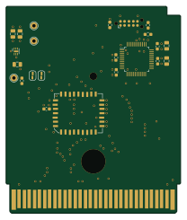 PIC
GB-CART256K-A
51.4 × 61 mm17 parts2LCC-BY-4.0379