
Tracker v1

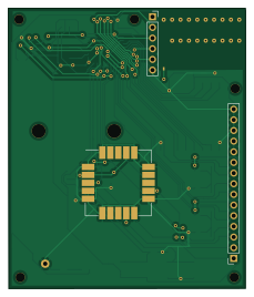
About the Tracker v1 PCB
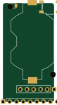
Tracker v1 is an open source STM32 PCB design by angelnu, published on GitHub under the MIT license. It is a 2-layer board measuring 56.5 × 66.8 mm, with 36 components from 20 distinct parts.
Its main chip is the STM32L412KB, from the STM32 family. Other key parts include the RFM95W-868S2, ublox_SAM-M8Q and LIS3DH. By type, the board carries 12 capacitors, 4 ICs, 2 connectors, 2 resistors, 1 transistor and 1 crystal.
It belongs with the sensors and rf & radio designs in this gallery.
From the project
LoraWan soil sensor
This is a GPS tracker including a move sensor and a distance sensor (not in the PCB). It also routes most of the MCU pins to a connector so additional sensors might be connected.
In this version a distance sensor is also used to measure the gasoil level in a vehicle.
This is Work In Progress - Firmware not ready and PCB not tested yet.
- Aisler PCB project - Tracker.sch - - - - - Traker.kicadpcb - Sensor: - GPS ubloxSAM-M8Q - low-power: 15 uA to keep memory and clock - most important factor for battery life - very quick on hotfix - 1s - supports GPS, Galileo and Glonax - high sesitivity -…
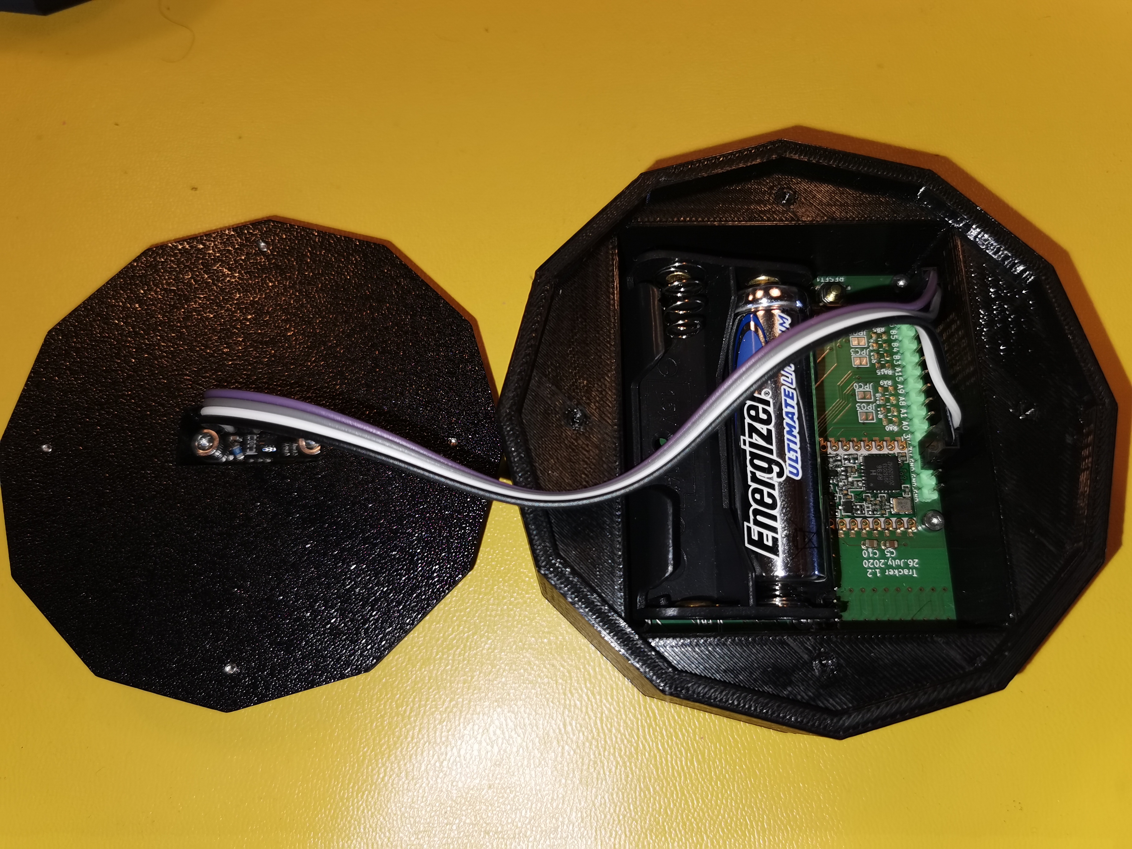
Main components on the Tracker v1
Tracker v1 bill of materials (BOM)
36 components, 20 distinct parts.
| Qty | Part | Footprint | Refs |
|---|---|---|---|
| 1 | STM32L412KB | LQFP-32_7x7mm_P0.8mm | U1 |
| 1 | RFM95W-868S2 | HOPERF_RFM9XW_SMD | U2 |
| 1 | ublox_SAM-M8Q | ublox_SAM-M8Q_HandSolder_plane | U3 |
| 1 | LIS3DH | LGA-16_3x3mm_P0.5mm_LayoutBorder3x5y | U4 |
| 1 | AO3401A | SOT-23 | Q1 |
| 1 | 32KHz | Crystal_SMD_3215-2Pin_3.2x1.5mm | Y1 |
| 1 | Conn_01x06_Male | PinSocket_1x06_P2.54mm_Vertical | J1 |
| 1 | Conn_01x09_Male | PinSocket_1x15_P2.54mm_Vertical | J2 |
| 1 | Antenna_Chip | Texas_SWRA416_868MHz_915MHz | AE1 |
| 1 | BOOT | SW_SPST_TL3342 | BOOT1 |
| 1 | Battery_Cell | BatteryHolder_HALJIA_2xAA | BT1 |
| 8 | PU | R_0805_2012Metric | RA0, RA1, RA8, RA9, RA15, RB3, RB4, RB5 |
| 1 | RESET | SW_SPST_TL3342 | RESET1 |
| 1 | LED | D_0805_2012Metric | D1 |
| 1 | Ferrite_Bead_Small | R_0805_2012Metric | FB1 |
| 2 | 10 pF | C_0805_2012Metric | C1, C2 |
| 7 | 100 nF | C_0805_2012Metric | C3, C4, C5, C6, C7, C9, C12 |
| 2 | 1 uF | C_0805_2012Metric | C8, C10 |
| 1 | 10 uF | C_0805_2012Metric | C11 |
| 2 | 12K | R_0805_2012Metric | R3, R7 |
Tracker v1 design files
The KiCad project lives in the angelnu/LorawanSensor repository on GitHub; these links point at the commit this page was built from.
Tracker v1: common questions
What microcontroller does the Tracker v1 use?
The Tracker v1 is built around the STM32L412KB, from the STM32 family.
How big is the Tracker v1 PCB?
The Tracker v1 measures 56.5 × 66.8 mm, has 2 copper layers and is 1.6 mm thick.
How many components are on the Tracker v1?
36 components, from 20 distinct parts. The full bill of materials is listed on this page.
Where can I download the Tracker v1 design files?
From the angelnu/LorawanSensor repository on GitHub, which has the KiCad layout; the links under Design files point to each one.
Can I use the Tracker v1 design in my own project?
Yes, under the terms of its MIT license, which angelnu chose for the repository.
Can I test firmware for the Tracker v1 without the hardware?
Yes. HardLabs builds a simulation of the board from its netlist and BOM, so you can run and debug STM32 firmware against it before you order a PCB.
More boards in LorawanSensor
Similar boards
 STM32
STM32LumenPnP Motherboard
opulo-inc
149 × 95 mm296 parts4LCC-BY-SA-4.03.7k STM32
STM32AxxSolder
AxxAxx
39 × 82.5 mm122 parts2LGPL-3.01.7k STM32
STM32AIOC
skuep
21 × 31.5 mm47 parts2LMIT1.4k STM32
STM32Ferris
pierrechevalier83
208.8 × 86.8 mm102 parts2LSHL-2.11.3k STM32
STM32176 pin board
rusefi
61.8 × 73.2 mm76 parts2LGPL-3.01.2k STM32
STM32Brain board STM32F407
61.8 × 73.2 mm69 parts2LGPL-3.01.2k