
Lpddr4-testbed

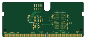
About the Lpddr4-testbed PCB
Lpddr4-testbed is an open source PCB design by antmicro, published on GitHub under the Apache-2.0 license. It is a 6-layer board measuring 69.6 × 30 mm, with 64 components from 14 distinct parts.
Other key parts include the PCA6408APW, AT24CS01-ST, MT53E1G32D2NP-046 WT:A and TPS613221ADBVT. By type, the board carries 39 capacitors, 13 resistors, 4 ICs, 4 diodes, 3 test points and 1 inductor.
It belongs with the dev boards & breakouts designs in this gallery.
From the project
Experimental breakout board for a signle 200-ball WFBGA LPDDR4 chip in SO-DIMM DDR4 form factor.
This repository contains open hardware design files for an experimental test module in a form of SO-DIMM DDR4 module. The module includes a standard 200-ball WFBGA (10mm × 14.5mm × 0.8mm, Ø0.35 SMD) LPDDR4 RAM footprint break-routed in the SO-DOMM edge connector. The design files were prepared in KiCad. Please note that this board is not electrically compatible with off-the-shelf SO-DIMM DDR4 memory modules. It is compatible with this LPDDR4 test platform.
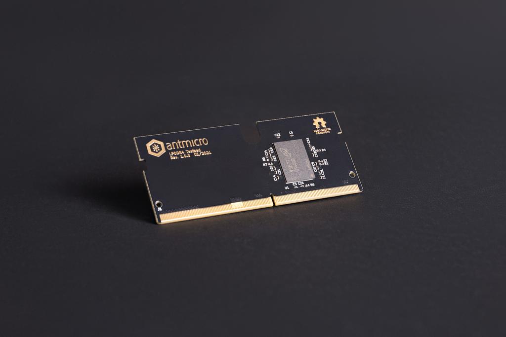
Main components on the Lpddr4-testbed
Lpddr4-testbed bill of materials (BOM)
64 components, 14 distinct parts.
| Qty | Part | Footprint | Refs |
|---|---|---|---|
| 1 | PCA6408APW PCA6408A_TSSOP NXP | TSSOP-16_4.4x5mm_P0.65mm | IC1 |
| 1 | AT24CS01-ST AT24CS01_SOT23 Atmel | SOT-23-5 | IC2 |
| 1 | MT53E1G32D2NP-046 WT:A MT53E1G32D2NP-046 Micron Technology | BGA-264-200_10x14.5mm_Layout12x22_P0.8x0.65mm | U1 |
| 1 | TPS613221ADBVT TPS613221A_SOT-23-5 Texas Instruments | SOT-23-5 | U2 |
| 3 | TP_0.75mm_SMD | TP_SMD_0.75mm | TP1, TP2, TP3 |
| 4 | KP-1608CGCK LED_G_0603_KP-1608CGCK Kingbright | LED_0603_1608Metric_G | D1, D2, D3, D4 |
| 1 | 1285AS-H-2R2M=P2 L_2u2_1.5A_1285AS-H Murata | L_0806_2016Metric | L1 |
| 35 | CC0201KRX6S5BB104 C_100n_0201 YAGEO | C_0201 | C1, C2, C3, C4, C5, C6, C7, C8 +27 |
| 2 | GRM155R61A475MEAAD C_4u7_0402 Murata | C_0402_1005Metric | C34, C37 |
| 2 | 0402X104K6R3CT C_100n_0402 Walsin | C_0402_1005Metric | C38, C39 |
| 6 | CRCW040210K0FKEDHP R_10k_0402 VISHAY | R_0402_1005Metric | R1, R3, R4, R5, R13, R14 |
| 2 | ERJ2GE0R00X R_0R_0402 PANASONIC | R_0402_1005Metric | R2, R7 |
| 1 | ERJ2GEJ241X R_240R_0402 PANASONIC | R_0402_1005Metric | R6 |
| 4 | ERJ2GEJ221X R_220R_0402 Panasonic | R_0402_1005Metric | R9, R10, R11, R12 |
Lpddr4-testbed design files
The KiCad project lives in the antmicro/lpddr4-testbed repository on GitHub; these links point at the commit this page was built from.
- Layoutlpddr4-testbed.kicad_pcb
- Schematiclpddr4-testbed.kicad_sch
Lpddr4-testbed: common questions
How big is the Lpddr4-testbed PCB?
The Lpddr4-testbed measures 69.6 × 30 mm, has 6 copper layers and is 1.6 mm thick.
How many components are on the Lpddr4-testbed?
64 components, from 14 distinct parts. The full bill of materials is listed on this page.
Where can I download the Lpddr4-testbed design files?
From the antmicro/lpddr4-testbed repository on GitHub, which has the KiCad layout and the schematic; the links under Design files point to each one.
Can I use the Lpddr4-testbed design in my own project?
Yes, under the terms of its Apache-2.0 license, which antmicro chose for the repository.
Similar boards
88 Pin Vag Breakout
rusefi
142 × 58 mm91 parts2LGPL-3.01.2k
134pin 7-967288-1
139.7 × 73.7 mm38 parts2LGPL-3.01.2k
Breakout 60pin EEC-IV
139.7 × 62.2 mm15 parts2LGPL-3.01.2k
Breakout 112pin Connector
174 × 58 mm39 parts2LGPL-3.01.2k
Eecv breakout
140.8 × 53.7 mm9 parts4LGPL-3.01.2k
Rj45 breakout
rene-dev
15.2 × 53.8 mm3 parts2LGPL-3.0979