
TI MSPM0-PCB-Design

About the TI MSPM0-PCB-Design
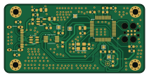
TI MSPM0-PCB-Design is an open source PCB design by ashfaque-ur-rahman, published on GitHub. It is a 2-layer board measuring 53 × 26 mm, with 30 components from 13 distinct parts.
Other key parts include the MPSM0G3507SPTR, USBLC6-2SC6, SPX3819M5-L-3-3, CH340E and LIS2DHTR. By type, the board carries 15 capacitors, 8 resistors, 5 ICs, 1 crystal and 1 connector.
It belongs with the test & measurement designs in this gallery.
From the project
Texas Instruments MSPM0 microcontroller PCB design — KiCad 2-layer board based on Phil's Lab tutorial
A Texas Instruments MSPM0G3507 microcontroller board designed in KiCad, based on the Phil's Lab MSPM0 PCB design tutorial series. This design marked my first experience with a non-ST microcontroller and the TI ecosystem — expanding beyond STM32 into a different ARM Cortex-M0+ platform with a modern USB-C interface and TagConnect debug port.
The TC2030 is a footprint-only debug connector — no physical connector is soldered. A spring-loaded TagConnect cable clips directly onto the PCB pads, keeping the board compact and eliminating an unnecessary through-hole connector.
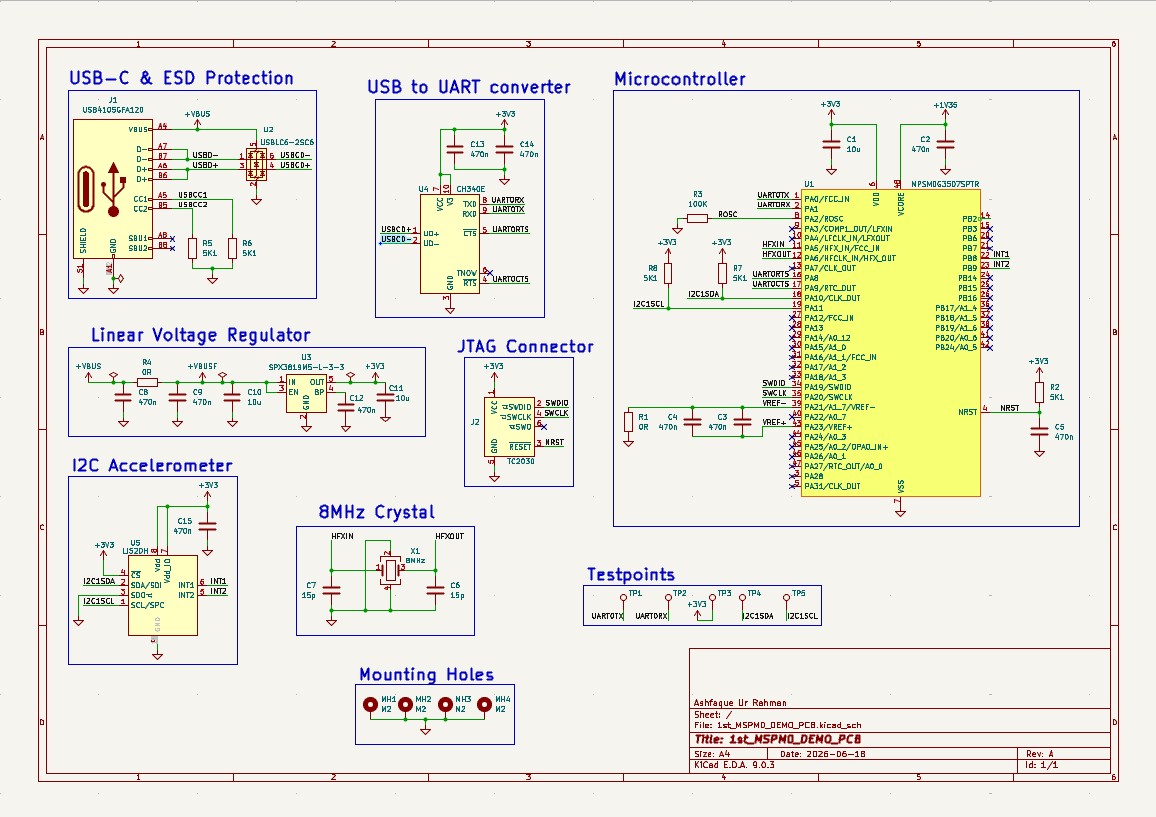
Main components on the TI MSPM0-PCB-Design
TI MSPM0-PCB-Design bill of materials (BOM)
30 components, 13 distinct parts.
| Qty | Part | Footprint | Refs |
|---|---|---|---|
| 1 | MPSM0G3507SPTR | LQFP-48_7x7mm_P0.5mm | U1 |
| 1 | USBLC6-2SC6 | SOT-23-6 | U2 |
| 1 | SPX3819M5-L-3-3 | SOT-23-5 | U3 |
| 1 | CH340E | MSOP-10_3x3mm_P0.5mm | U4 |
| 1 | LIS2DHTR LIS2DH | LGA-14_2x2mm_P0.35mm_LayoutBorder3x4y | U5 |
| 1 | X32258MOB4SI 8MHz | Crystal_SMD_3225-4Pin_3.2x2.5mm | X1 |
| 1 | USB4105GFA120 | USB_C_Receptacle_GCT_USB4105-xx-A_16P_TopMnt_Horizontal | J1 |
| 3 | CL21B106KPQNNNE 10u | C_0805_2012Metric | C1, C10, C11 |
| 10 | CL10A474KB8NNNC 470n | C_0603_1608Metric | C2, C3, C4, C5, C8, C9, C12, C13 +2 |
| 2 | CC0603JRNPO9BN150 15p | C_0603_1608Metric | C6, C7 |
| 2 | RC0603JR-070RL 0R | R_0603_1608Metric | R1, R4 |
| 5 | ERA3AED512V 5K1 | R_0603_1608Metric | R2, R5, R6, R7, R8 |
| 1 | ARG03BTC1003 100K | R_0603_1608Metric | R3 |
TI MSPM0-PCB-Design design files
The KiCad project lives in the ashfaque-ur-rahman/TI_MSPM0-PCB-Design repository on GitHub; these links point at the commit this page was built from.
- Layout1st_MSPM0_DEMO_PCB.kicad_pcb
- Schematic1st_MSPM0_DEMO_PCB.kicad_sch
TI MSPM0-PCB-Design: common questions
How big is the TI MSPM0-PCB-Design?
The TI MSPM0-PCB-Design measures 53 × 26 mm, has 2 copper layers and is 1.6 mm thick.
How many components are on the TI MSPM0-PCB-Design?
30 components, from 13 distinct parts. The full bill of materials is listed on this page.
Where can I download the TI MSPM0-PCB-Design design files?
From the ashfaque-ur-rahman/TI_MSPM0-PCB-Design repository on GitHub, which has the KiCad layout and the schematic; the links under Design files point to each one.
Can I use the TI MSPM0-PCB-Design design in my own project?
The repository has no license, so all rights stay with ashfaque-ur-rahman. Use it as a reference, and ask the author before reusing the design.
Similar boards
LevelShifter
gusmanb
28.3 × 39.8 mm21 parts2LGPL-3.05.0k
StackLink
52.3 × 10.5 mm5 parts2LGPL-3.05.0k
AnalyzerBoxPCB fork
52.7 × 47.9 mm54 parts4LGPL-3.05.0k
EleLab v2 Bus100
Chrismettal
100 × 100 mm37 parts2LGPL-3.0528
EleLab v2 Bus150
150 × 50 mm37 parts2LGPL-3.0528
EleLab v2 PowerFeed
68 × 50 mm11 parts2LGPL-3.0528