
Temperature sensors

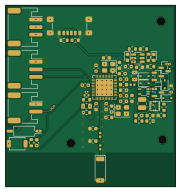
About the Temperature sensors PCB
Temperature sensors is an open source Nordic nRF PCB design by askiiart, published on GitHub. It is a 6-layer board measuring 45 × 48 mm, with 66 components from 45 distinct parts.
Its main chip is the nRF52840-QFXX, from the Nordic nRF family. Other key parts include the TP4057 and SN74LVC1G00DCK. By type, the board carries 23 capacitors, 12 resistors, 6 diodes, 5 inductors, 4 ICs and 4 connectors.
It belongs with the sensors and iot & wireless designs in this gallery.
From the project
Some futurely-Zigbee temperature sensors; I dislike the thermostat disagreeing with me, so I will make my own.
An nRF52840-based Zigbee temperature sensor for use with ESPHome, designed for peak battery efficiency.
I've gotten rather sick of my room being hot, meanwhile the thermostat is just across the wall, showing 5+ degrees cooler, even with my computer only idling. So instead of being "reasonable", I decided to make some temperature sensors so I could track it properly and figure out how to deal with the issue. Granted this is just a pretty boring temperature sensor, but what makes it unique is the lengths I went to for battery efficiency (while being reasonable, not compromising on features…
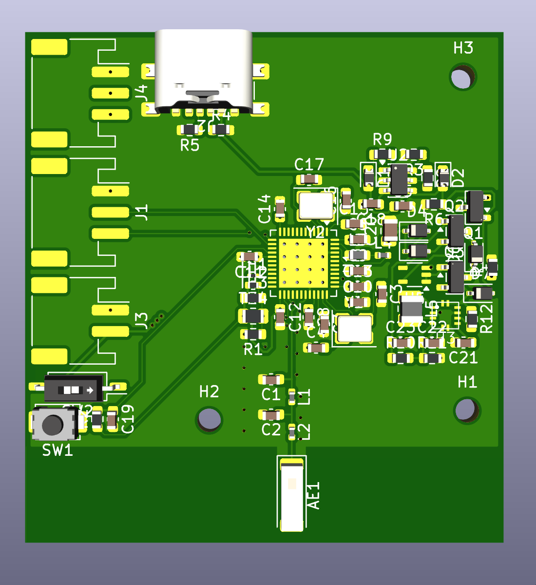
Main components on the Temperature sensors
Temperature sensors bill of materials (BOM)
66 components, 45 distinct parts — part numbers from the project's BOM.
| Qty | Part | Footprint | Refs |
|---|---|---|---|
| 1 | nRF52840-QFXX | QFN-48-1EP_6x6mm_P0.4mm_EP4.6x4.6mm_ThermalVias | U1 |
| 1 | TP4057 | TSOT-23-6 | U2 |
| 1 | ~ | TPS63051-QFN-12-HotRod | U3 |
| 1 | SN74LVC1G00DCK | Texas_R-PDSO-G5_DCK-5 | U5 |
| 3 | AO3401A | SOT-23 | Q1, Q2, Q3 |
| 1 | 32MHz | Crystal_SMD_3225-4Pin_3.2x2.5mm | Y1 |
| 1 | 32.768kHz | Crystal_SMD_3225-4Pin_3.2x2.5mm | Y2 |
| 2 | Conn_01x03 | JST_PH_S3B-PH-SM4-TB_1x03-1MP_P2.00mm_Horizontal | J1, J4 |
| 1 | USB_C_Receptacle_PowerOnly_6P | USB_C_Receptacle_GCT_USB4135-GF-A_6P_TopMnt_Horizontal | J2 |
| 1 | Conn_01x02 | JST_PH_S2B-PH-SM4-TB_1x02-1MP_P2.00mm_Horizontal | J3 |
| 1 | Antenna_Chip | Johanson_2450AT43F0100 | AE1 |
| 1 | SW_Push | SW_SPST_TS-1088-xR020 | SW1 |
| 1 | SW_SPST | SW_DIP_SPSTx01_Slide_Copal_CHS-01B_W7.62mm_P1.27mm | SW2 |
| 1 | Thermistor_NTC | R_0201_0603Metric | TH1 |
| 1 | Thermistor_NTC | R_0402_1005Metric | TH2 |
| 1 | Thermistor_NTC | R_0603_1608Metric | TH3 |
| 1 | Thermistor_NTC | R_0805_2012Metric | TH4 |
| 2 | LED | D_0603_1608Metric | D1, D2 |
| 2 | D_Small | D_SOD-323 | D3, D4 |
| 2 | D | D_SOD-323 | D6, D7 |
Show 25 more
| Qty | Part | Footprint | Refs |
|---|---|---|---|
| 1 | 4.7nH | L_0402_1005Metric | L1 |
| 1 | 2.2nH | L_0402_1005Metric | L2 |
| 1 | 10uH | L_0603_1608Metric | L3 |
| 1 | 15nH | L_0402_1005Metric | L4 |
| 1 | 1.5uH | L_1008_2520Metric | L5 |
| 1 | 1.0pF | C_0603_1608Metric | C1 |
| 1 | 1.2pF | C_0603_1608Metric | C2 |
| 2 | 20pF | C_0603_1608Metric | C3, C4 |
| 3 | 10uF | C_0603_1608Metric | C5, C18, C23 |
| 2 | 1.0uF | C_0603_1608Metric | C6, C9 |
| 2 | 100pF | C_0603_1608Metric | C7, C15 |
| 1 | DNP | C_0603_1608Metric | C8 |
| 1 | 47nF | C_0603_1608Metric | C10 |
| 5 | 100nF | C_0603_1608Metric | C11, C12, C13, C14, C19 |
| 2 | 15pF | C_0603_1608Metric | C16, C17 |
| 1 | 100uF | C_0805_2012Metric | C20 |
| 1 | 1nF | C_0603_1608Metric | C21 |
| 1 | 10pF | C_0603_1608Metric | C22 |
| 3 | 1M | R_0603_1608Metric | R1, R7, R12 |
| 2 | 10k | R_0603_1608Metric | R2, R3 |
| 2 | 5.1k | R_0603_1608Metric | R4, R5 |
| 1 | 100k | R_0603_1608Metric | R6 |
| 2 | 300 | R_0603_1608Metric | R8, R9 |
| 1 | 560k | R_0603_1608Metric | R10 |
| 1 | 180k | R_0603_1608Metric | R11 |
Temperature sensors design files
The KiCad project lives in the askiiart/temperature-sensors repository on GitHub; these links point at the commit this page was built from.
- Layouttemperature-sensors.kicad_pcb
- Schematictemperature-sensors.kicad_sch
- BOMBOM.csv
Temperature sensors: common questions
What microcontroller does the Temperature sensors use?
The Temperature sensors is built around the nRF52840-QFXX, from the Nordic nRF family.
How big is the Temperature sensors PCB?
The Temperature sensors measures 45 × 48 mm, has 6 copper layers and is 1.6 mm thick.
How many components are on the Temperature sensors?
66 components, from 45 distinct parts, with part numbers taken from the project's own BOM. The full bill of materials is listed on this page.
Where can I download the Temperature sensors design files?
From the askiiart/temperature-sensors repository on GitHub, which has the KiCad layout, the schematic and the BOM; the links under Design files point to each one.
Can I use the Temperature sensors design in my own project?
The repository has no license, so all rights stay with askiiart. Use it as a reference, and ask the author before reusing the design.
Can I test firmware for the Temperature sensors without the hardware?
Yes. HardLabs builds a simulation of the board from its netlist and BOM, so you can run and debug Nordic nRF firmware against it before you order a PCB.
Similar boards
 Nordic nRF
Keyboard
byrantech
262.5 × 109.6 mm206 parts2LMIT4.3k Nordic nRF
TOTEM
GEIGEIGEIST
258.8 × 94.4 mm85 parts2LCERN-OHL-P-2.02.0k Nordic nRF
Pixl.js
solosky
40 × 23 mm45 parts4LGPL-2.01.4k Nordic nRF
Management
dennisss
101 × 31.5 mm50 parts2LApache-2.0381 Nordic nRF
Board
363 × 128 mm420 parts4LApache-2.0381 Nordic nRF
Board hl15-latest
61 × 37 mm14 parts2LApache-2.0381