
Kicad rfm95-breakout board

About the Kicad rfm95-breakout board
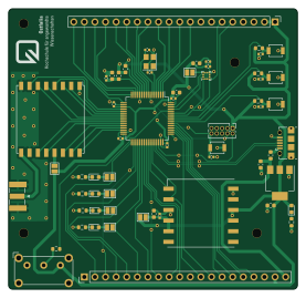
Kicad rfm95-breakout board is an open source STM32 PCB design by Bamelink, published on GitHub. It is a 2-layer board measuring 69.2 × 67 mm, with 60 components from 28 distinct parts.
Its main chip is the STM32L053R8T6, from the STM32 family. Other key parts include the AMS1117-3.3, RFM95W-868S2, LIS2HH12 and L80-R. By type, the board carries 21 capacitors, 9 resistors, 7 jumpers, 5 ICs, 5 connectors and 5 switches.
It belongs with the rf & radio, sensors and dev boards & breakouts designs in this gallery.
From the project
A developer board created in kicad featuring a STM32L053 MCU, RFM95W LoRa chip, LR-80 GPS and a MEMS Sensor
Move the position file from the geber folder to the main project folder, open a command prompt and execute:
Zip the gerber folder and now you have the new files ready for JLCPCB.

Main components on the Kicad rfm95-breakout board
Kicad rfm95-breakout board bill of materials (BOM)
60 components, 28 distinct parts — part numbers from the project's BOM.
| Qty | Part | Footprint | Refs |
|---|---|---|---|
| 1 | AMS1117-3.3 | SOT-223-3_TabPin2 | U100 |
| 1 | STM32L053R8T6 | LQFP-64_10x10mm_P0.5mm | U500 |
| 1 | RFM95W-868S2 | HOPERF_RFM9XW_SMD | U600 |
| 1 | LIS2HH12 | LGA-12_2x2mm_P0.5mm | U700 |
| 1 | L80-R | Quectel_L80-R | U800 |
| 1 | CRYSTAL_GND24 Crystal_GND24 | Crystal_SMD_3225-4Pin_3.2x2.5mm | Y500 |
| 1 | C239059 ARM 10pin | PinHeader_2x05_P1.27mm_Vertical | J5 |
| 1 | C132563 USB_B_Micro | USB_Micro-B_Amphenol_10118194_Horizontal | J100 |
| 2 | C50981 Male Pinheader 1x20 | PinHeader_1x20_P2.54mm_Vertical | J300, J301 |
| 1 | Conn_Coaxial | SMA_Samtec_SMA-J-P-X-ST-EM1_EdgeMount | J600 |
| 7 | SolderJumper_2_Open | SolderJumper-2_P1.3mm_Open_Pad1.0x1.5mm | JP400, JP401, JP402, JP403, JP600, JP700, JP800 |
| 3 | SW_Push | SW_SPST_B3U-1000P | SW400, SW401, SW402 |
| 1 | C231329 Reset_Switch | SW_SPST_B3U-1000P | SW500 |
| 1 | BOOT0_SWITCH BOOT0_Switch | SW_E-Switch_EG1224_SPDT_Angled | SW501 |
| 3 | C434420 GREEN | LED_0603_1608Metric | D100, D400, D401 |
| 1 | C375446 BLUE | LED_0603_1608Metric | D402 |
| 1 | C389517 RED | LED_0603_1608Metric | D403 |
| 1 | 100R | L_0603_1608Metric | FB100 |
| 1 | 120R | L_0603_1608Metric | FB200 |
| 2 | 22U 22u | C_0603_1608Metric | C100, C101 |
Show 8 more
| Qty | Part | Footprint | Refs |
|---|---|---|---|
| 2 | 10U 10u | C_0603_1608Metric | C200, C700 |
| 11 | 100N 100n | C_0402_1005Metric | C201, C202, C203, C204, C400, C401, C402, C500 +3 |
| 3 | 1u | C_0603_1608Metric | C205, C206, C800 |
| 1 | 10N 10n | C_0402_1005Metric | C207 |
| 2 | 10P 10p | C_0402_1005Metric | C501, C502 |
| 1 | 1K5 1k5 | R_0603_1608Metric | R100 |
| 4 | 1k | R_0603_1608Metric | R400, R401, R402, R403 |
| 4 | 10K 10k | R_0603_1608Metric | R404, R405, R406, R500 |
Kicad rfm95-breakout board design files
The KiCad project lives in the Bamelink/kicad-rfm95-breakout-board repository on GitHub; these links point at the commit this page was built from.
Kicad rfm95-breakout board: common questions
What microcontroller does the Kicad rfm95-breakout board use?
The Kicad rfm95-breakout board is built around the STM32L053R8T6, from the STM32 family.
How big is the Kicad rfm95-breakout board?
The Kicad rfm95-breakout board measures 69.2 × 67 mm, has 2 copper layers and is 1.6 mm thick.
How many components are on the Kicad rfm95-breakout board?
60 components, from 28 distinct parts, with part numbers taken from the project's own BOM. The full bill of materials is listed on this page.
Where can I download the Kicad rfm95-breakout board design files?
From the Bamelink/kicad-rfm95-breakout-board repository on GitHub, which has the KiCad layout, the schematic and the BOM; the links under Design files point to each one.
Can I use the Kicad rfm95-breakout board design in my own project?
The repository has no license, so all rights stay with Bamelink. Use it as a reference, and ask the author before reusing the design.
Can I test firmware for the Kicad rfm95-breakout board without the hardware?
Yes. HardLabs builds a simulation of the board from its netlist and BOM, so you can run and debug STM32 firmware against it before you order a PCB.
Similar boards
 STM32
STM32LumenPnP Motherboard
opulo-inc
149 × 95 mm296 parts4LCC-BY-SA-4.03.7k STM32
STM32AxxSolder
AxxAxx
39 × 82.5 mm122 parts2LGPL-3.01.7k STM32
STM32AIOC
skuep
21 × 31.5 mm47 parts2LMIT1.4k STM32
STM32Ferris
pierrechevalier83
208.8 × 86.8 mm102 parts2LSHL-2.11.3k STM32
STM32176 pin board
rusefi
61.8 × 73.2 mm76 parts2LGPL-3.01.2k STM32
STM32Brain board STM32F407
61.8 × 73.2 mm69 parts2LGPL-3.01.2k