
Telemetry System

About the Telemetry System PCB
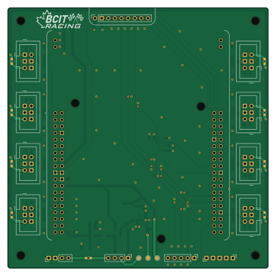
Telemetry System is an open source PCB design by BCIT-BAJA, published on GitHub. It is a 4-layer board measuring 99.9 × 99.9 mm, with 88 components from 22 distinct parts.
Other key parts include the NUCLEO-L476RG, LMR51606XDBVR, MPU-6500 and 3070. By type, the board carries 25 resistors, 22 capacitors, 18 diodes, 9 fuses, 8 connectors and 4 ICs.
It belongs with the rf & radio designs in this gallery.
From the project
The telemetry system for BCIT-BAJA car, collects strain across suspension components of car to allow BAJA to optimize material and reinforce weak areas of suspension. As well as collect other data such as linear/angular acceleration.
The telemetry system for BCIT-BAJA car, collects strain across suspension components of car to allow BAJA to optimize material and reinforce weak areas of suspension. As well as collect other data such as linear/angular acceleration.
There consists of 2 parts of this project.
PART B the amplification of the (-15-15mV) analog strain signal to (0-3.0V) which is then routed to
Main components on the Telemetry System
Telemetry System bill of materials (BOM)
88 components, 22 distinct parts.
| Qty | Part | Footprint | Refs |
|---|---|---|---|
| 1 | NUCLEO-L476RG STMicroelectronics | MODULE_NUCLEO-L476RG | U1 |
| 1 | LMR51606XDBVR LMR51603XFDBVR Texas Instruments | LMR51603XFDBVR_DBV0006A-MFG-IPC_C | U2 |
| 1 | MPU-6500 TDK InvenSense | MPU-6500_QFN40P300X300X95-25N | U3 |
| 1 | 3070 Adafruit 3070 Adafruit Industries LLC | Adafruit3070 | U4 |
| 1 | ZXMP10A13FTA PMOS Diodes Incorporated | TSOT-23 | Q3 |
| 8 | BHR-06-VUA IDC 6Pin Male Header Adam Tech | AdamTech_BHR-06-VUA | J6, J7, J8, J9, J10, J11, J12, J13 |
| 1 | F0603E0R37FSTR FAST-BLOW 375mA 32V 0.45Ω KYOCERA AVX | Fuse_0603_1608Metric_Pad1.05x0.95mm_HandSolder | F1 |
| 8 | F0603G0R02FNTR 70mA 5s Fusing, 7.5 Ohms KYOCERA AVX | Fuse_0603_1608Metric_Pad1.05x0.95mm_HandSolder | F2, F3, F4, F5, F6, F7, F8, F9 |
| 18 | DDZ9684-7 D_Zener_Small Diodes Incorporated | D_SOD-123 | D1, D2, D3, D4, D5, D6, D7, D8 +10 |
| 1 | LQH44PH151MPRL 150uH Murata Electronics | LQH44PH151MPRL_IND_LQH44PN_PR_MUR-M | L1 |
| 5 | CL31A226KAHNNNE 22uF ±10% Samsung Electro-Mechanics | C_1206_3216Metric_Pad1.33x1.80mm_HandSolder | C1, C20, C21, C22, C24 |
| 2 | CL21B105KBFNNNE 1uF, X7R Samsung Electro-Mechanics | C_0805_2012Metric_Pad1.18x1.45mm_HandSolder | C2, C4 |
| 4 | CL21B104KCFNNNE 0.1uF ±10%, X7R Samsung Electro-Mechanics | C_0805_2012Metric_Pad1.18x1.45mm_HandSolder | C3, C7, C10, C14 |
| 1 | CL31B106KAHNNNE 10uF, X7R Samsung Electro-Mechanics | C_1206_3216Metric_Pad1.33x1.80mm_HandSolder | C5 |
| 9 | CL10B682KB8NNNC 6.8nF ±10% Samsung Electro-Mechanics | C_0603_1608Metric_Pad1.08x0.95mm_HandSolder | C6, C8, C9, C11, C13, C15, C16, C17 +1 |
| 1 | CL10B103KB8WPND 10nF ±10%, Ceramic, X7R, >4V Samsung Electro-Mechanics | C_0603_1608Metric_Pad1.08x0.95mm_HandSolder | C12 |
| 1 | CRCW08050000Z0EA 0 Vishay Dale | ZeroOhmSwitch_R_0805_2012Metric_Pad1.20x1.40mm_HandSolder | R1 |
| 8 | CRCW0805100RFKEA 100 ±1% Vishay Dale | R_0805_2012Metric_Pad1.20x1.40mm_HandSolder | R2, R11, R13, R15, R17, R19, R21, R23 |
| 1 | CRCW080576K8FKEA 76.8K+- 1%, ±100ppm/°C Vishay Dale | R_0805_2012Metric_Pad1.20x1.40mm_HandSolder | R3 |
| 1 | CRCW080510K0FKEAC 10K +-1%, ±100ppm/°C Vishay Dale | R_0805_2012Metric_Pad1.20x1.40mm_HandSolder | R4 |
Show 2 more
| Qty | Part | Footprint | Refs |
|---|---|---|---|
| 6 | CRCW080510K0FKEA 10K ±1% Vishay Dale | R_0805_2012Metric_Pad1.20x1.40mm_HandSolder | R5, R6, R7, R8, R9, R25 |
| 8 | CRCW08051M00FKEA 1M ±1% Vishay Dale | R_0805_2012Metric_Pad1.20x1.40mm_HandSolder | R12, R14, R16, R18, R20, R22, R24, R26 |
Telemetry System design files
The KiCad project lives in the BCIT-BAJA/BCIT-BAJA-DAQ repository on GitHub; these links point at the commit this page was built from.
Telemetry System: common questions
How big is the Telemetry System PCB?
The Telemetry System measures 99.9 × 99.9 mm, has 4 copper layers and is 1.547 mm thick.
How many components are on the Telemetry System?
88 components, from 22 distinct parts. The full bill of materials is listed on this page.
Where can I download the Telemetry System design files?
From the BCIT-BAJA/BCIT-BAJA-DAQ repository on GitHub, which has the KiCad layout and the schematic; the links under Design files point to each one.
Can I use the Telemetry System design in my own project?
The repository has no license, so all rights stay with BCIT-BAJA. Use it as a reference, and ask the author before reusing the design.
More boards in BCIT-BAJA-DAQ
Similar boards
Hat
pa3gsb
65 × 56 mm81 parts2LNo license675
Radioberry juice
65 × 56 mm87 parts2LNo license675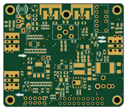
Radioberry preamp
65 × 56 mm137 parts2LNo license675
Goodwatch20
travisgoodspeed
25.6 × 27.6 mm20 parts2LNo license568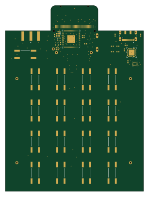
GoodPocketWatch
75.2 × 101.2 mm56 parts2LNo license568
Goodwatch31
25.6 × 27.6 mm23 parts2LNo license568