
4-layer panel

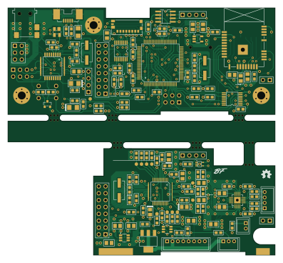
About the 4-layer panel PCB
4-layer panel is an open source AVR/Arduino PCB design by bfrigon, published on GitHub under the CC-BY-SA-4.0 license. It is a 2-layer board measuring 99.1 × 91.4 mm, with 90 components from 37 distinct parts.
Its main chip is the ATMEGA2560-16AU, from the AVR/Arduino family. Other key parts include the DS3231MZ, ATMEGA16U2-AU, ATWINC1500-MR210PB, CD74HC4050PWR and AP2112K-3.3. By type, the board carries 34 capacitors, 24 resistors, 10 connectors, 7 ICs, 6 inductors and 2 crystals.
It belongs with the iot & wireless and displays & leds designs in this gallery.
From the project
Alarm clock (v3)
- Arduino based design using the ATMEGA2560 MCU. - Plays MP3/WAV files from a SD card. - WiFi connectivity (802.11 b/g/n) - Automatic clock synchronization using NTP - Send alarm state to Home Assistant via MQTT - Large RGB seven segment display - 16x2 character LCD display - Night lamp - Touch keypad - 24h battery backup
Home Assistant -------------- The clock can send the alarm switch state and next alarm timestamp to Home Assistant via MQTT. This allows to run home automations based on the alarm time. It also sends other data such as WiFi signal strength, power state, battery voltage and…
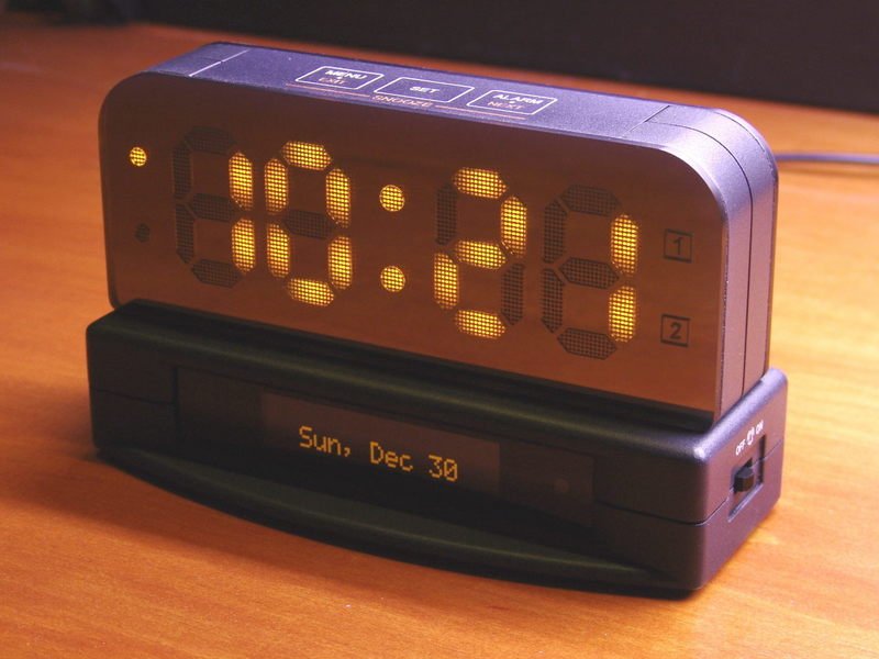
Main components on the 4-layer panel
4-layer panel bill of materials (BOM)
90 components, 37 distinct parts.
| Qty | Part | Footprint | Refs |
|---|---|---|---|
| 1 | ATMEGA2560-16AU | QFP-14-100 | U1 |
| 1 | DS3231MZ | SOIC8 | U2 |
| 1 | ATMEGA16U2-AU | QFP-7-32 | U3 |
| 1 | ATWINC1500-MR210PB | ATWINC1500-MR | U4 |
| 2 | CD74HC4050PWR | TSSOP16 | U5, U7 |
| 1 | AP2112K-3.3 | SOT23-5 | U6 |
| 1 | MMST3904 | SOT23 | Q1 |
| 2 | 16.00 MHz | smt-CSM-3X-7x4mm | Y1, Y2 |
| 1 | - | CUI-P1J-021-SMT | J1 |
| 1 | USB-MINI-B | USB-MB_UX60SC-MB-5ST | J2 |
| 1 | DB-B | HDR-M-1x04 | J3 |
| 2 | ICSP | HDR-M-2x03 | J4, J7 |
| 1 | Micro_SD | MOLEX-MICROSD-475710001 | J5 |
| 1 | PSU-SIG | HDR-M-1x04 | J6 |
| 1 | DB-A | HDR-M-2x08 | J9 |
| 1 | PSU | HDR-M-2x03 | J10 |
| 1 | DB-C | HDR-M-1x02 | J12 |
| 1 | CR1220 | S8411-45R | B1 |
| 1 | SR05 | SOT-143 | DA1 |
| 1 | 500mA | R-1206 | F1 |
Show 17 more
| Qty | Part | Footprint | Refs |
|---|---|---|---|
| 1 | RESET | B3F-10XX | SW1 |
| 2 | CD1206-S01575 | D-1206 | D1, D2 |
| 2 | 2508053007Y0 | FER-0805 | L1, L2 |
| 4 | MPZ1608S221A | FER-0603 | L3, L4, L5, L6 |
| 4 | 20pF | C-0603 | C1, C2, C7, C8 |
| 15 | 100nF | C-0603 | C3, C5, C6, C9, C10, C11, C14, C22 +7 |
| 3 | 1uF | C-0805 | C4, C19, C20 |
| 1 | 22pF | C-0603 | C12 |
| 1 | 1uF | C-0603 | C13 |
| 1 | 10nF | C-0603 | C15 |
| 5 | 10uF | C-0805 | C16, C17, C18, C21, C28 |
| 4 | 1nF | C-0603 | C31, C32, C33, C34 |
| 9 | 10k | R-0603 | R1, R2, R5, R6, R9, R11, R20, R21 +1 |
| 2 | 22 | R-0603 | R3, R4 |
| 2 | 1M | R-0603 | R7, R8 |
| 8 | 100k | R-0603 | R10, R12, R13, R14, R15, R16, R17, R18 |
| 3 | 1k | R-0603 | R19, R23, R24 |
4-layer panel design files
The KiCad project lives in the bfrigon/alarm-clock-v3 repository on GitHub; these links point at the commit this page was built from.
4-layer panel: common questions
What microcontroller does the 4-layer panel use?
The 4-layer panel is built around the ATMEGA2560-16AU, from the AVR/Arduino family.
How big is the 4-layer panel PCB?
The 4-layer panel measures 99.1 × 91.4 mm, has 2 copper layers and is 1.6 mm thick.
How many components are on the 4-layer panel?
90 components, from 37 distinct parts. The full bill of materials is listed on this page.
Where can I download the 4-layer panel design files?
From the bfrigon/alarm-clock-v3 repository on GitHub, which has the KiCad layout; the links under Design files point to each one.
Can I use the 4-layer panel design in my own project?
Yes, under the terms of its CC-BY-SA-4.0 license, which bfrigon chose for the repository.
Can I test firmware for the 4-layer panel without the hardware?
Yes. HardLabs builds a simulation of the board from its netlist and BOM, so you can run and debug AVR/Arduino firmware against it before you order a PCB.
More boards in alarm-clock-v3
 AVR/Arduino
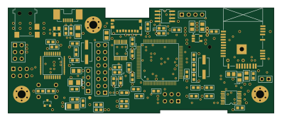
Motherboard
99.1 × 39.4 mm76 parts2LCC-BY-SA-4.018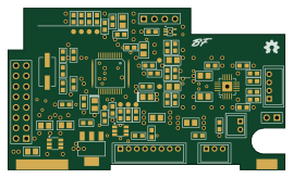
Daughterboard
67.3 × 39.4 mm73 parts2LCC-BY-SA-4.018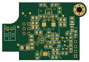
Psu
44.5 × 30.5 mm40 parts2LCC-BY-SA-4.018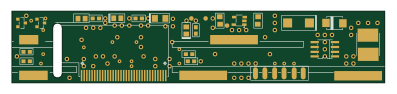
Front Panel
99.1 × 19.1 mm23 parts2LCC-BY-SA-4.018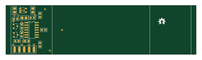
Touch keypad
99.1 × 25.4 mm19 parts2LCC-BY-SA-4.018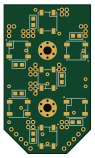
Display - RGB Seven Seg. Digit
22.9 × 39.4 mm16 parts2LCC-BY-SA-4.018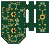
Panel rgb digits
43.8 × 39.4 mm16 parts2LCC-BY-SA-4.018
Level shifter
21.6 × 24.1 mm10 parts2LCC-BY-SA-4.018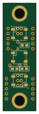
Rgb lamp
12.7 × 40.6 mm6 parts2LCC-BY-SA-4.018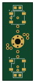
Rgb dots
11.4 × 29.2 mm4 parts2LCC-BY-SA-4.018
Similar boards
 AVR/Arduino
Magspoof
samyk
35 × 29 mm11 parts2LNo license4.2k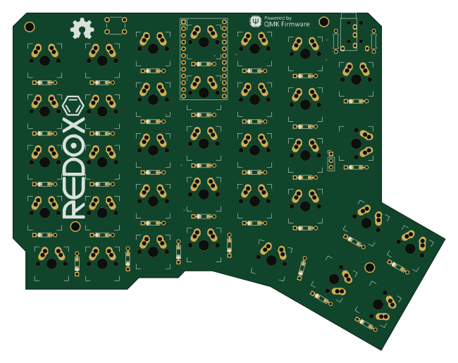 AVR/Arduino
Redox keyboard
mattdibi
162.2 × 126.5 mm77 parts2LMIT2.0k AVR/Arduino
Labrador
espotek-org
36.8 × 34.7 mm75 parts2LNo license1.2k AVR/Arduino
V4
stuartpittaway
30 × 50 mm38 parts2LCC-BY-NC-4.01.1k AVR/Arduino
ModuleV450
30 × 61.4 mm39 parts2LCC-BY-NC-4.01.1k AVR/Arduino
Discipline
coseyfannitutti
304.9 × 122.8 mm170 parts2LCC-BY-NC-4.01.0k