
ExitIQ

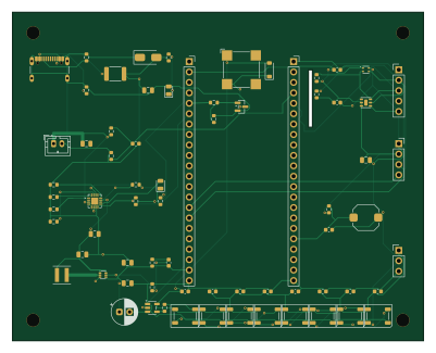
About the ExitIQ PCB
ExitIQ is an open source PCB design by Binita126, published on GitHub under the MIT license. It is a 2-layer board measuring 100 × 80 mm, with 39 components from 21 distinct parts.
Other key parts include the BQ24074RGTR, TPS61023DRLR, 74AHCT1G125, SHT40-AD1B and SGP40-DIS. By type, the board carries 8 LEDs, 5 ICs, 2 connectors, 1 transistor, 1 buzzer and 1 fuse.
It belongs with the displays & leds, power & battery and sensors designs in this gallery.
From the project
ExitIQ: ESP32-S3 Edge-AI Emergency Evacuation Guidance Terminal (Vishwakarma Awards 2026 Stage 2)
ExitIQ is an ESP32-S3-powered, decentralized Edge AI emergency evacuation guidance terminal designed to replace obsolete static signage with real-time, dynamic egress routing during smoke and fire emergencies.
Conventional fire evacuation systems rely on static exit signs and centralized alarms. In modern multi-story and industrial facilities, static signage presents critical failure modes: 1. Blind Routing: Static signs guide occupants toward fixed exits regardless of whether the path is blocked by thermal barriers or smoke. 2. Panic Bottlenecks: Occupants blindly funnel into primary…
Main components on the ExitIQ
ExitIQ bill of materials (BOM)
39 components, 21 distinct parts — part numbers from the project's BOM.
| Qty | Part | Footprint | Refs |
|---|---|---|---|
| 1 | BQ24074RGTR | QFN-16-1EP_3x3mm_P0.5mm_EP1.7x1.7mm | U2 |
| 1 | TPS61023DRLR | SOT-563 | U3 |
| 1 | 74AHCT1G125 | SOT-23-5 | U4 |
| 1 | SHT40-AD1B | Sensirion_DFN-4_1.5x1.5mm_P0.8mm_SHT4x_NoCentralPad | U5 |
| 1 | SGP40-DIS | Sensirion_DFN-6-1EP_2.44x2.44mm_P0.8mm | U6 |
| 1 | 2N7002 | SOT-23 | Q1 |
| 1 | USB_C_5V_IN | USB_C_Receptacle_GCT_USB4105-xx-A_16P_TopMnt_Horizontal | J1 |
| 1 | BATT_JST_PH | JST_PH_B2B-PH-K_1x02_P2.00mm_Vertical | J2 |
| 1 | CMT-8540S-SMT | MagneticBuzzer_CUI_CMT-8504-100-SMT | BZ1 |
| 2 | 22uF 10V | C_0805_2012Metric | C_BO1, C_BO2 |
| 8 | 100nF | C_0603_1608Metric | C_LED1, C_LED2, C_LED3, C_LED4, C_LED5, C_LED6, C_LED7, C_LED8 |
| 1 | 2.0A Hold | Fuse_1812_4532Metric | F1 |
| 3 | 100k 1% | R_0603_1608Metric | R_BAT1, R_BAT2, R_FB2 |
| 2 | 5.1k | R_0603_1608Metric | R_CC1, R_CC2 |
| 1 | 10k | R_0603_1608Metric | R_EN2 |
| 1 | 732k 1% | R_0603_1608Metric | R_FB1 |
| 1 | TEST_BTN | SW_Push_1TS009xxxx-xxxx-xxxx_6x6x5mm | SW1 |
| 8 | WS2812B | LED_WS2812B_PLCC4_5.0x5.0mm_P3.2mm | LED1, LED2, LED3, LED4, LED5, LED6, LED7, LED8 |
| 1 | SMAJ5.0A | D_SMA | D1 |
| 1 | 1.0uH 4.5A | L_Coilcraft_XxL4020 | L1 |
Show 1 more
| Qty | Part | Footprint | Refs |
|---|---|---|---|
| 1 | 10uF 16V | C_0805_2012Metric | C1 |
ExitIQ design files
The KiCad project lives in the Binita126/ExitIQ repository on GitHub; these links point at the commit this page was built from.
ExitIQ: common questions
How big is the ExitIQ PCB?
The ExitIQ measures 100 × 80 mm, has 2 copper layers and is 1.6 mm thick.
How many components are on the ExitIQ?
39 components, from 21 distinct parts, with part numbers taken from the project's own BOM. The full bill of materials is listed on this page.
Where can I download the ExitIQ design files?
From the Binita126/ExitIQ repository on GitHub, which has the KiCad layout and the BOM; the links under Design files point to each one.
Can I use the ExitIQ design in my own project?
Yes, under the terms of its MIT license, which Binita126 chose for the repository.
Similar boards
BM28B0.6-24DSBreakout
scottbez1
15.2 × 35.6 mm3 parts2LApache-2.022.2k
LevelShifterBreakout
15.2 × 20.3 mm5 parts2LApache-2.022.2k
View base
81.2 × 81.2 mm81 parts2LApache-2.022.2k
View screen
35 × 35 mm12 parts2LApache-2.022.2k
Display eval
byrantech
52.1 × 22.6 mm12 parts4LMIT4.3k
ChainlinkBase
98.4 × 190.5 mm119 parts2LApache-2.04.2k