
ML0

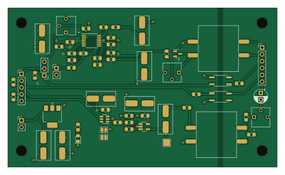
About the ML0 PCB
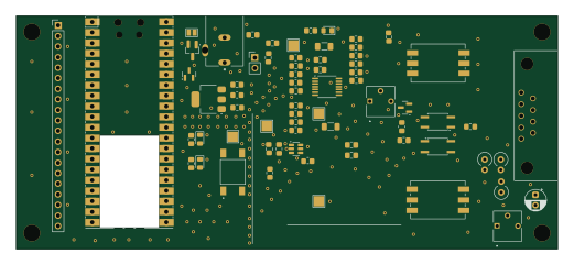
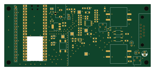
ML0 is an open source PCB design by brucemack, published on GitHub under the GPL-3.0 license. It is a 2-layer board measuring 100 × 59 mm, with 60 components from 49 distinct parts.
Other key parts include the TLV9164PWR, LTV-356T, LM1117MP-3.3, MCP4725A0T-E/CH and LMV324. By type, the board carries 20 capacitors, 20 resistors, 6 ICs, 5 connectors, 2 jumpers and 2 transformers.
It belongs with the rf & radio designs in this gallery.
From the project
An open source EchoLink/AllStarLink implementation that runs on a simple microcontroller.
Is it possible to build a full EchoLink® node using a $6 microcontroller? I'm not completely sure, but let's find out. The goal of this project is to create the smallest, cheapest way to put a radio onto the EchoLink network. If you are new to the world of EchoLink please see the official website for complete information. EchoLink is a peer-to-peer VoIP (voice over IP) network used to link amateur radio stations across the Internet.
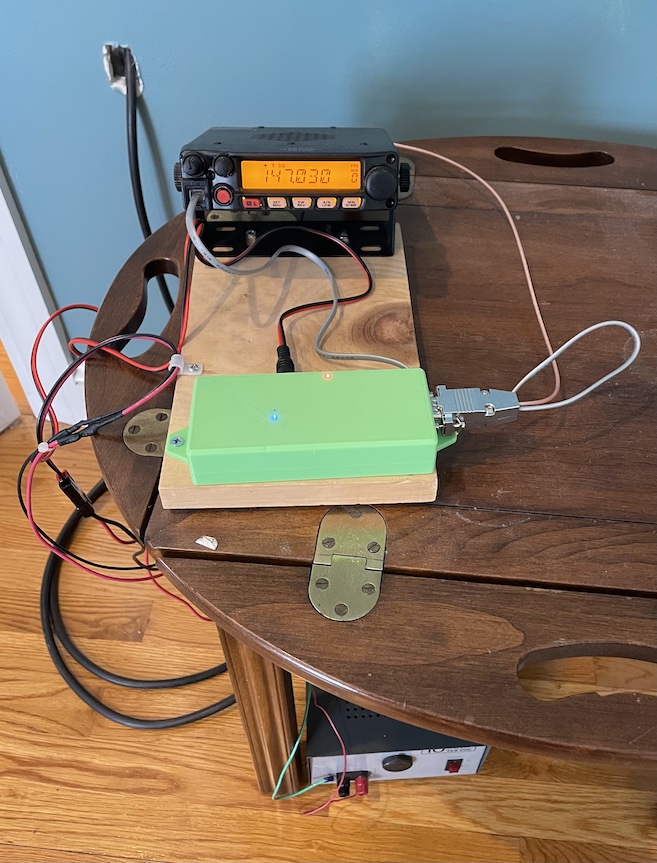
Main components on the ML0
ML0 bill of materials (BOM)
60 components, 49 distinct parts — part numbers from the project's BOM.
| Qty | Part | Footprint | Refs |
|---|---|---|---|
| 1 | TLV9164PWR LMV321 | SOT-23-5_HandSoldering | U1 |
| 2 | LTV-356T | SO-4_4.4x3.6mm_P2.54mm | U2, U5 |
| 1 | LM1117MP-3.3 NCP1117-3.3_SOT223 | SOT-223-3_TabPin2 | U3 |
| 1 | MCP4725A0T-E/CH MCP4725xxx-xCH | SOT-23-6 | U4 |
| 1 | LMV324 | TSSOP-14_4.4x5mm_P0.65mm | U9 |
| 1 | DE9_RECEPTACLE Conn_01x06 | PinHeader_1x06_P2.54mm_Vertical | J1 |
| 1 | PJ-102AH 12V Supply | PinHeader_1x02_P2.54mm_Vertical | J2 |
| 1 | CONN_01X20 Digital Connector | PinHeader_1x05_P2.54mm_Vertical | J3 |
| 1 | CONN_01X02 ADC Connector | PinHeader_1x02_P2.54mm_Vertical | J4 |
| 1 | Conn_01x03 | PinHeader_1x03_P2.54mm_Vertical | J5 |
| 1 | DAC Address Control | SolderJumper-2_P1.3mm_Bridged_Pad1.0x1.5mm | JP1 |
| 1 | SolderJumper_2_Open | SolderJumper-2_P1.3mm_Open_Pad1.0x1.5mm | JP2 |
| 1 | 50K 10k | POT_3362P | RV1 |
| 2 | 10k | POT_3362P | RV3, RV4 |
| 2 | Transformer_1P_1S | CheapAudioTransformer | T1, T2 |
| 1 | C84256 LED | LED_0805_2012Metric_Pad1.15x1.40mm_HandSolder | D1 |
| 1 | BAT54S | SOT-23 | D2 |
| 1 | 22U 100u | CAP_KEMET_530_530 | C1 |
| 1 | 22U 0.1u | C_0805_2012Metric_Pad1.18x1.45mm_HandSolder | C2 |
| 2 | 22N 22n | C_0805_2012Metric_Pad1.18x1.45mm_HandSolder | C3, C26 |
Show 29 more
| Qty | Part | Footprint | Refs |
|---|---|---|---|
| 2 | 10N 10n | C_0805_2012Metric_Pad1.18x1.45mm_HandSolder | C4, C27 |
| 1 | 47U 0.1u | C_0805_2012Metric_Pad1.18x1.45mm_HandSolder | C5 |
| 1 | 0.1U 100u | CAP_KEMET_530_530 | C6 |
| 3 | 47U 10u | CAP_KEMET_530_530 | C7, C8, C9 |
| 1 | C22320 47u (Optional DC Block) | CP_Radial_D5.0mm_P2.50mm | C10 |
| 1 | 47U 1u | C_0805_2012Metric_Pad1.18x1.45mm_HandSolder | C17 |
| 2 | 0.1U 0.1u | C_0805_2012Metric_Pad1.18x1.45mm_HandSolder | C18, C21 |
| 1 | 47U 47u | CAP_KEMET_530_530 | C19 |
| 1 | 47U 100u | CAP_KEMET_530_530 | C20 |
| 1 | NC | C_0805_2012Metric_Pad1.18x1.45mm_HandSolder | C22 |
| 1 | 47u | CAP_KEMET_530_530 | C24 |
| 1 | 0.1u | C_0805_2012Metric_Pad1.18x1.45mm_HandSolder | C29 |
| 2 | 1.5K 1.5k | R_0805_2012Metric_Pad1.20x1.40mm_HandSolder | R1, R15 |
| 1 | 2.7K 2.7k | R_0805_2012Metric_Pad1.20x1.40mm_HandSolder | R2 |
| 1 | C17477 1k | R_0805_2012Metric_Pad1.20x1.40mm_HandSolder | R3 |
| 1 | 620 200 | R_0805_2012Metric_Pad1.20x1.40mm_HandSolder | R4 |
| 2 | 2.2K 10k | R_0805_2012Metric_Pad1.20x1.40mm_HandSolder | R5, R6 |
| 1 | 220 | R_0805_2012Metric_Pad1.20x1.40mm_HandSolder | R7 |
| 1 | 220 0R | R_0805_2012Metric_Pad1.20x1.40mm_HandSolder | R8 |
| 1 | 1k | R_0805_2012Metric_Pad1.20x1.40mm_HandSolder | R9 |
| 1 | C17629 270k | R_0805_2012Metric_Pad1.20x1.40mm_HandSolder | R10 |
| 1 | C17589 270k | R_0805_2012Metric_Pad1.20x1.40mm_HandSolder | R11 |
| 2 | 2.2K 2.2k | R_0805_2012Metric_Pad1.20x1.40mm_HandSolder | R12, R13 |
| 1 | 2.2k | R_0805_2012Metric_Pad1.20x1.40mm_HandSolder | R14 |
| 1 | 2.7K 22k | R_0805_2012Metric_Pad1.20x1.40mm_HandSolder | R16 |
| 1 | 100 2.7k | R_0805_2012Metric_Pad1.20x1.40mm_HandSolder | R17 |
| 1 | C17477 0R | R_0805_2012Metric_Pad1.20x1.40mm_HandSolder | R18 |
| 1 | 220 1k | R_0805_2012Metric_Pad1.20x1.40mm_HandSolder | R19 |
| 1 | 100 570 | R_0805_2012Metric_Pad1.20x1.40mm_HandSolder | R20 |
ML0 design files
The KiCad project lives in the brucemack/microlink repository on GitHub; these links point at the commit this page was built from.
- Layouthw/ML0/ML0.kicad_pcb
- Schematichw/ML0/ML0.kicad_sch
- BOMhw/ML4/ML4-bom.csv
ML0: common questions
How big is the ML0 PCB?
The ML0 measures 100 × 59 mm, has 2 copper layers and is 1.6 mm thick.
How many components are on the ML0?
60 components, from 49 distinct parts, with part numbers taken from the project's own BOM. The full bill of materials is listed on this page.
Where can I download the ML0 design files?
From the brucemack/microlink repository on GitHub, which has the KiCad layout, the schematic and the BOM; the links under Design files point to each one.
Can I use the ML0 design in my own project?
Yes, under the terms of its GPL-3.0 license, which brucemack chose for the repository.
More boards in microlink
Similar boards

Radioberry preamp
pa3gsb
65 × 56 mm137 parts2LNo license675
Radioberry juice
65 × 56 mm87 parts2LNo license675
Hat
65 × 56 mm81 parts2LNo license675
Open smartwatch light
Open-Smartwatch
36.1 × 36.1 mm51 parts4LGPL-3.0246
Open smartwatch gps
45 × 41 mm67 parts4LGPL-3.0241
Misrc v2.5-rounded
Stefan-Olt
150 × 90 mm318 parts4LCC-BY-4.0231