
PCB

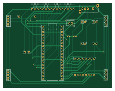
About the PCB
PCB is an open source RP2040/RP2350 PCB design by bsce26023, published on GitHub under the MIT license. It is a 2-layer board measuring 100 × 78 mm, with 20 components from 9 distinct parts.
Its main chip is the RaspberryPi_Pico, from the RP2040/RP2350 family. By type, the board carries 2 resistors, 1 module, 1 connector and 1 switch.
It belongs with the robotics & motion, power & battery and sensors designs in this gallery.
From the project
This repo is for a line following robot. I've designed this robot keeping in mind that this could be used in competitions. It is designed for high speed performance and complex line following
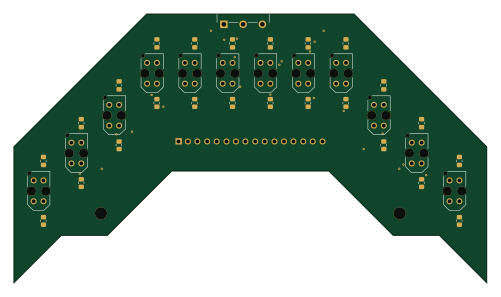
Hi! I wanted to make a Line Following Robot(LFR) and I visited some shops and online marketplaces but I couldn't find a good, fast, compact and accurate robot with a reasonable price. So, I created a LFR from scratch including the PCBs for main board and sensor array for the hardware part and code in 5 separate files. Now I will explain Components, Wiring, Coding, and sensor array separately.
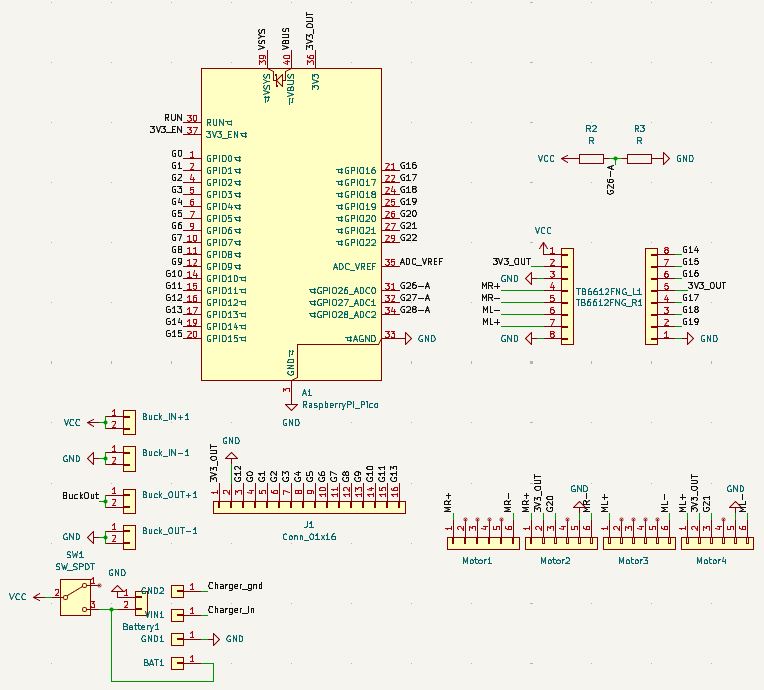
Main components on the PCB
PCB bill of materials (BOM)
20 components, 9 distinct parts.
| Qty | Part | Footprint | Refs |
|---|---|---|---|
| 1 | RaspberryPi_Pico | RaspberryPi_Pico_Common_THT | A1 |
| 1 | Conn_01x16 | PinHeader_1x16_P2.54mm_Horizontal | J1 |
| 4 | Conn_01x01 | PinHeader_1x01_P2.54mm_Vertical | BAT1, GND1, GND2, VIN1 |
| 1 | Conn_01x02 | JST_XH_B2B-XH-A_1x02_P2.50mm_Vertical | Battery1 |
| 4 | Conn_01x02 | PinHeader_1x02_P2.54mm_Vertical | Buck_IN+1, Buck_IN-1, Buck_OUT+1, Buck_OUT-1 |
| 4 | Conn_01x06 | JST_ZH_B6B-ZR_1x06_P1.50mm_Vertical | Motor1, Motor2, Motor3, Motor4 |
| 1 | SW_SPDT | SW_Slide_SP3T_Straight_CK_OS103012MU1QP1 | SW1 |
| 2 | Conn_01x08 | PinHeader_1x08_P2.54mm_Vertical | TB6612FNG_L1, TB6612FNG_R1 |
| 2 | R | R_0805_2012Metric_Pad1.20x1.40mm_HandSolder | R2, R3 |
PCB design files
The KiCad project lives in the bsce26023/Line-Following-Robot repository on GitHub; these links point at the commit this page was built from.
- LayoutPCB/PCB.kicad_pcb
- SchematicPCB/PCB.kicad_sch
PCB: common questions
What microcontroller does the PCB use?
The PCB is built around the RaspberryPi_Pico, from the RP2040/RP2350 family.
How big is the PCB?
The PCB measures 100 × 78 mm, has 2 copper layers and is 1.6 mm thick.
How many components are on the PCB?
20 components, from 9 distinct parts. The full bill of materials is listed on this page.
Where can I download the PCB design files?
From the bsce26023/Line-Following-Robot repository on GitHub, which has the KiCad layout and the schematic; the links under Design files point to each one.
Can I use the PCB design in my own project?
Yes, under the terms of its MIT license, which bsce26023 chose for the repository.
Can I test firmware for the PCB without the hardware?
Yes. HardLabs builds a simulation of the board from its netlist and BOM, so you can run and debug RP2040/RP2350 firmware against it before you order a PCB.
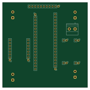
More boards in Line-Following-Robot
Similar boards
 RP2040/RP2350
Open Book Abridged Edition
joeycastillo
85 × 115 mm29 parts2LCC-BY-SA-4.08.1k RP2040/RP2350
Corne
foostan
277.2 × 107.5 mm164 parts2LCC-BY-4.07.7k RP2040/RP2350
Corne
277.2 × 107.5 mm164 parts2LCC-BY-4.07.7k RP2040/RP2350
LogicAnalyzer
gusmanb
57 × 55.2 mm6 parts2LGPL-3.05.0k RP2040/RP2350
Jitx design
55.5 × 65 mm26 parts4LGPL-3.05.0k RP2040/RP2350
Pro V2
kata0510
290.1 × 130 mm270 parts2LMIT2.3k