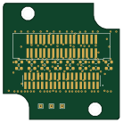
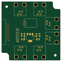
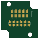
Trigger board

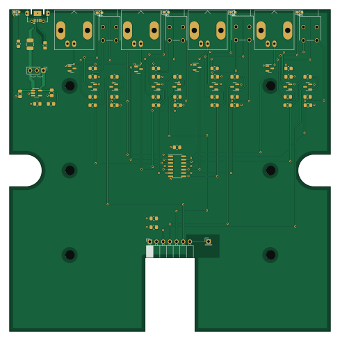
About the Trigger board
Trigger board is an open source PCB design by BUNPC, published on GitHub. It is a 2-layer board measuring 122 × 122.3 mm, with 70 components from 36 distinct parts.
Other key parts include the SN74HCS00 and MIC5318. By type, the board carries 28 resistors, 9 diodes, 9 capacitors, 8 transistors, 6 connectors and 4 switches.
From the project
Repository for the storage and dissemination of NN22 technical documents
This is a remote wireless trigger/IO box for the ninjaNIRS system.
polarity marks on LED fix up silkscreen and add text
2023-08-07 Testing Rev 2.0 board with wireless link
All good. Only issue is that channels 3 and 4 are swapped.
2023-05-22 Look at Hammond box 1593XAL. Nope! Maybe 1598B?
Proceed with new design for Hammond box Add an LDO on USB power input to run on e.g. 4.1V Adjust component values, update a few circuit issues Measure I-V curve on logic inputs to radio Tx, ensure 2N3904 can drive them
Main components on the Trigger board
Trigger board bill of materials (BOM)
70 components, 36 distinct parts — part numbers from the project's BOM.
| Qty | Part | Footprint | Refs |
|---|---|---|---|
| 1 | SN74HCS00 | SOIC-14_3.9x8.7mm_P1.27mm | U1 |
| 1 | MIC5318 | SOT-23-5_HandSoldering | U2 |
| 8 | MMBT3904 | SOT-23 | Q1, Q2, Q3, Q4, Q5, Q6, Q7, Q8 |
| 4 | Conn_Coaxial | BNC_Amphenol_B6252HB-NPP3G-50_Horizontal | J1, J2, J3, J4 |
| 1 | USB_B_Micro | USB_Micro-AB_Molex_47590-0001 | J5 |
| 1 | Conn_01x07 | PinSocket_1x07_P2.54mm_Horizontal | J6 |
| 1 | Antenna | PinHeader_1x01_P2.54mm_Vertical | AE1 |
| 1 | 801-43-007-20-001000 Jumper_3_Open Mill-Max | PinHeader_1x03_P2.54mm_Vertical | JP1 |
| 1 | Hammond 1598BBK | Hammond_1598B | N1 |
| 4 | SW_Push | 800SP9B6M6RE | SW1, SW2, SW3, SW4 |
| 5 | LED | LED_0603_marked | D1, D2, D3, D4, D5 |
| 4 | BAV99 | SOT-23 | D6, D7, D8, D9 |
| 1 | FerriteBead_Small | L_1210_3225Metric_Pad1.42x2.65mm_HandSolder | FB1 |
| 2 | CL32B106KOULNNE 47nF Samsung | C_0805_2012Metric_Pad1.18x1.45mm_HandSolder | C1, C4 |
| 2 | C0805C104M3RACTU 47nF Kemet | C_0805_2012Metric_Pad1.18x1.45mm_HandSolder | C2, C3 |
| 2 | C0805C473K3RACTU 1uF Kemet | C_0805_2012Metric_Pad1.18x1.45mm_HandSolder | C5, C6 |
| 1 | C0805C473K3RACTU 0.1uF Kemet | C_0805_2012Metric_Pad1.18x1.45mm_HandSolder | C7 |
| 1 | C0805C473K3RACTU 10uF Kemet | C_0805_2012Metric_Pad1.18x1.45mm_HandSolder | C8 |
| 1 | CL32B106KOULNNE 0.1uF Samsung | C_0805_2012Metric_Pad1.18x1.45mm_HandSolder | C9 |
| 3 | RC1206FR-07100RL 10.0k 1% Yageo | R_0805_2012Metric_Pad1.20x1.40mm_HandSolder | R1, R16, R22 |
Show 16 more
| Qty | Part | Footprint | Refs |
|---|---|---|---|
| 3 | RC1206JR-071KL 100 Yageo | R_0805_2012Metric_Pad1.20x1.40mm_HandSolder | R2, R19, R26 |
| 1 | RC1206JR-0710KL 100 Yageo | R_0805_2012Metric_Pad1.20x1.40mm_HandSolder | R3 |
| 3 | RC1206JR-0710KL 10k Yageo | R_0805_2012Metric_Pad1.20x1.40mm_HandSolder | R4, R5, R6 |
| 3 | RC1206JR-0710KL 10.0k 1% Yageo | R_0805_2012Metric_Pad1.20x1.40mm_HandSolder | R7, R8, R10 |
| 1 | RC1206JR-0710KL 3.3k Yageo | R_0805_2012Metric_Pad1.20x1.40mm_HandSolder | R9 |
| 2 | RMCF1206FT39R0 10k Stackpole | R_0805_2012Metric_Pad1.20x1.40mm_HandSolder | R11, R14 |
| 1 | RMCF1206FT39R0 3.3k Stackpole | R_0805_2012Metric_Pad1.20x1.40mm_HandSolder | R12 |
| 1 | RMCF1206FT39R0 100 Stackpole | R_0805_2012Metric_Pad1.20x1.40mm_HandSolder | R13 |
| 2 | RC1206JR-071KL 10k Yageo | R_0805_2012Metric_Pad1.20x1.40mm_HandSolder | R15, R21 |
| 2 | RC1206JR-071KL 10.0k 1% Yageo | R_0805_2012Metric_Pad1.20x1.40mm_HandSolder | R17, R23 |
| 1 | RC1206FR-07100RL 3.3k Yageo | R_0805_2012Metric_Pad1.20x1.40mm_HandSolder | R18 |
| 1 | RC1206FR-07100RL 10k Yageo | R_0805_2012Metric_Pad1.20x1.40mm_HandSolder | R20 |
| 1 | RC1206JR-071KL 3.3k Yageo | R_0805_2012Metric_Pad1.20x1.40mm_HandSolder | R24 |
| 1 | RC1206JR-071KL 1k Yageo | R_0805_2012Metric_Pad1.20x1.40mm_HandSolder | R25 |
| 1 | 24.0k 1% | R_0805_2012Metric_Pad1.20x1.40mm_HandSolder | R27 |
| 1 | 10.0k 1% | R_0805_2012Metric_Pad1.20x1.40mm_HandSolder | R28 |
Trigger board design files
The KiCad project lives in the BUNPC/NN22-Technical-Documents repository on GitHub; these links point at the commit this page was built from.
- LayoutHardware Peripherial/ninjaNIRS Triggerbox/hardware/Rev2_KiCAD/trigger-board/trigger-board.kicad_pcb
- SchematicHardware Peripherial/ninjaNIRS Triggerbox/hardware/Rev2_KiCAD/trigger-board/trigger-board.kicad_sch
- BOMHardware Peripherial/ninjaNIRS Triggerbox/hardware/Rev1a_Eagle/T-Y16W206116A W206116ASY15-10sets-TriggerBox_Rev1a_BOM-Elsa2020.11.23.xlsx
Trigger board: common questions
How big is the Trigger board?
The Trigger board measures 122 × 122.3 mm, has 2 copper layers and is 1.6 mm thick.
How many components are on the Trigger board?
70 components, from 36 distinct parts, with part numbers taken from the project's own BOM. The full bill of materials is listed on this page.
Where can I download the Trigger board design files?
From the BUNPC/NN22-Technical-Documents repository on GitHub, which has the KiCad layout, the schematic and the BOM; the links under Design files point to each one.
Can I use the Trigger board design in my own project?
The repository has no license, so all rights stay with BUNPC. Use it as a reference, and ask the author before reusing the design.