
Heater

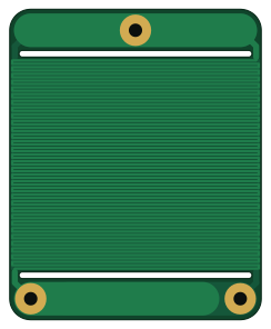
About the Heater PCB
Heater is an open source PCB design by c0pperdragon, published on GitHub. It is a 2-layer board measuring 60 × 74 mm, with 3 components from 1 distinct parts.
It belongs with the sensors designs in this gallery.
From the project
Cheap DIY solution to make a heater for hot-plate soldering.
Cheap DIY solution to make a heater for hot-plate soldering.
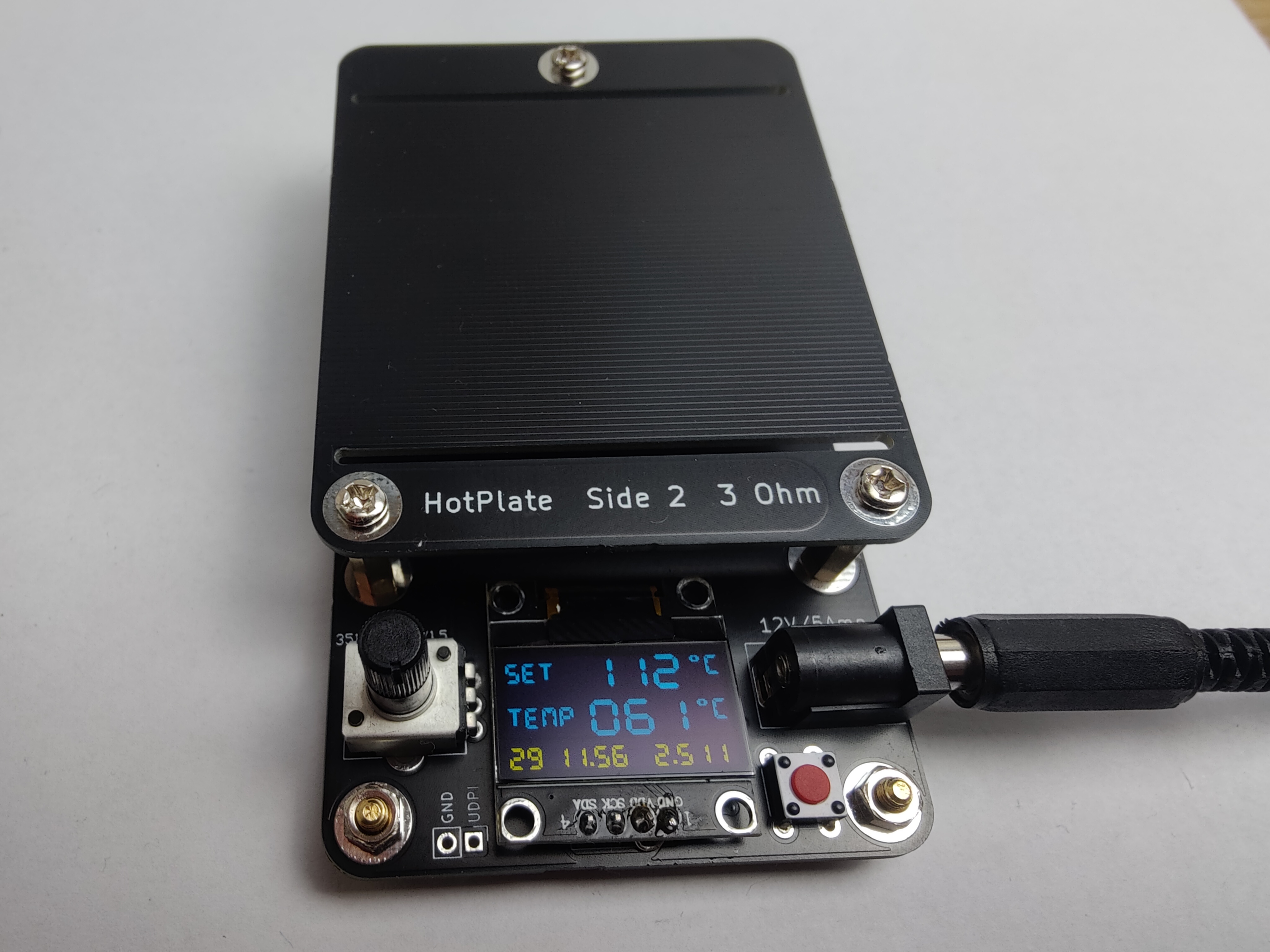
1. Plug the device to a common 12V DC power source that is able to provide 5 ampere. 2. Place the object to be soldered on the heater plate. 3. Switch on the heater with the red power button. 4. Select a target temperature (the "Set" value on the display) with the potentiometer. 5. When the solder is molten enough, turn off the heater with the red button. Note that there is no support to automatically follow a temperature profile.
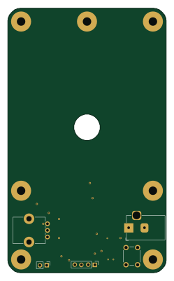
Heater bill of materials (BOM)
3 components, 1 distinct parts.
| Qty | Part | Footprint | Refs |
|---|---|---|---|
| 3 | Conn_01x01 | MountingHole_3.2mm_Large | JBOTTOM1, JGND1, JTOP1 |
Heater design files
The KiCad project lives in the c0pperdragon/HotPlate repository on GitHub; these links point at the commit this page was built from.
- Layoutheater/heater.kicad_pcb
- Schematicheater/heater.kicad_sch
Heater: common questions
How big is the Heater PCB?
The Heater measures 60 × 74 mm, has 2 copper layers and is 1.6 mm thick.
How many components are on the Heater?
3 components, from 1 distinct parts. The full bill of materials is listed on this page.
Where can I download the Heater design files?
From the c0pperdragon/HotPlate repository on GitHub, which has the KiCad layout and the schematic; the links under Design files point to each one.
Can I use the Heater design in my own project?
The repository has no license, so all rights stay with c0pperdragon. Use it as a reference, and ask the author before reusing the design.
More boards in HotPlate
Similar boards
Sensor smd
scottbez1
40 × 20 mm5 parts2LApache-2.04.2k
Sensors
StuckAtPrototype
15.2 × 9 mm14 parts4LApache-2.03.8k
Microphone
Mentra-Community
5.5 × 6.1 mm6 parts2LMIT1.2k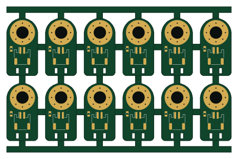
TemperaturePCB PANEL
stuartpittaway
116 × 75.5 mm178 parts2LCC-BY-NC-4.01.1k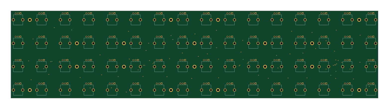
Pots
shanteacontrols
390 × 93 mm75 parts2LApache-2.0956
USB
52 × 12.6 mm6 parts2LApache-2.0956