
CTS-Ground-Station-UHF-Antenna-Switch

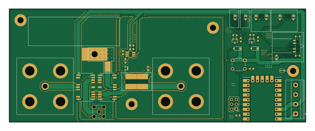
About the CTS-Ground-Station-UHF-Antenna-Switch PCB
CTS-Ground-Station-UHF-Antenna-Switch is an open source RP2040/RP2350 PCB design by CalgaryToSpace, published on GitHub under the Apache-2.0 license. It is a 2-layer board measuring 157.2 × 60 mm, with 42 components from 22 distinct parts.
Its main chip is the RP2040-Zero, from the RP2040/RP2350 family. Other key parts include the LTC5507ES6 and PAT1220-C-10DB. By type, the board carries 15 resistors, 9 diodes, 5 connectors, 4 capacitors, 3 ICs and 2 transistors.
It belongs with the rf & radio designs in this gallery.
From the project
PCB and firmware for a ground station UHF antenna switch (between high-power uplink and low-noise downlink, via a single antenna)
PCB and firmware for a ground station UHF antenna switch (between high-power uplink and low-noise downlink, via a single antenna).
This is a high-power UHF antenna switch PCB (for separate RX/TX paths), controlled with automatic TX sensing.
Rev 1 PCB works and is deployed at the CalgaryToSpace ground station as of 2026-05-26.
Rev 2 PCB is under development, though it is only a small incremental improvement over Rev 1. Main goal with Rev 2 is to improve the isolation performance.
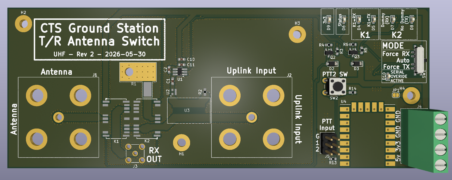
Main components on the CTS-Ground-Station-UHF-Antenna-Switch
CTS-Ground-Station-UHF-Antenna-Switch bill of materials (BOM)
42 components, 22 distinct parts.
| Qty | Part | Footprint | Refs |
|---|---|---|---|
| 1 | LTC5507ES6 | TSOT-23-6_HandSoldering | U1 |
| 1 | PAT1220-C-10DB | RF_Attenuator_Susumu_PAT1220 | U2 |
| 1 | RP2040-Zero | RP2040 Zero | U4 |
| 2 | 2N7002 | SOT-23 | Q2, Q3 |
| 1 | Conn_N_Type_Female | Amphenol N Jack 172234 | J1 |
| 1 | Conn_SO-239 | Amphenol N Jack 172234 | J2 |
| 1 | Conn_SMA_Female | SMA_Amphenol_901-144_Vertical | J3 |
| 1 | Screw_Terminal_01x04 | TerminalBlock_Phoenix_MKDS-1,5-4-5.08_1x04_P5.08mm_Horizontal | J4 |
| 1 | Conn_02x03_Odd_Even | PinHeader_2x03_P2.54mm_Vertical | J5 |
| 2 | HF3-51 | Relay_SPDT_AXICOM_HF3Series_50ohms_Pitch1.27mm | K1, K2 |
| 1 | SW_SP3T | SW_SP3T_PCM13 | SW1 |
| 1 | SW_Push | SW_PUSH_6mm_H4.3mm | SW2 |
| 2 | 1N4148W | D_SOD-123 | D2, D3 |
| 7 | LED | LED_0603_1608Metric_Pad1.05x0.95mm_HandSolder | D4, D5, D6, D7, D8, D9, D10 |
| 3 | 100p | C_0603_1608Metric_Pad1.08x0.95mm_HandSolder | C1, C2, C11 |
| 1 | 100n | C_0603_1608Metric_Pad1.08x0.95mm_HandSolder | C10 |
| 1 | I100N50X4B | I100N50X4B-On-PCB | R1 |
| 1 | 50 | R_0603_1608Metric_Pad0.98x0.95mm_HandSolder | R2 |
| 2 | 100 | R_0603_1608Metric_Pad0.98x0.95mm_HandSolder | R3, R5 |
| 2 | 10k | R_0603_1608Metric_Pad0.98x0.95mm_HandSolder | R4, R6 |
Show 2 more
| Qty | Part | Footprint | Refs |
|---|---|---|---|
| 4 | 3k9 | R_0603_1608Metric_Pad0.98x0.95mm_HandSolder | R7, R9, R11, R15 |
| 5 | 4k7 | R_0603_1608Metric_Pad0.98x0.95mm_HandSolder | R8, R10, R12, R13, R14 |
CTS-Ground-Station-UHF-Antenna-Switch design files
The KiCad project lives in the CalgaryToSpace/CTS-Ground-Station-UHF-Antenna-Switch repository on GitHub; these links point at the commit this page was built from.
CTS-Ground-Station-UHF-Antenna-Switch: common questions
What microcontroller does the CTS-Ground-Station-UHF-Antenna-Switch use?
The CTS-Ground-Station-UHF-Antenna-Switch is built around the RP2040-Zero, from the RP2040/RP2350 family.
How big is the CTS-Ground-Station-UHF-Antenna-Switch PCB?
The CTS-Ground-Station-UHF-Antenna-Switch measures 157.2 × 60 mm, has 2 copper layers and is 1.6 mm thick.
How many components are on the CTS-Ground-Station-UHF-Antenna-Switch?
42 components, from 22 distinct parts. The full bill of materials is listed on this page.
Where can I download the CTS-Ground-Station-UHF-Antenna-Switch design files?
From the CalgaryToSpace/CTS-Ground-Station-UHF-Antenna-Switch repository on GitHub, which has the KiCad layout and the schematic; the links under Design files point to each one.
Can I use the CTS-Ground-Station-UHF-Antenna-Switch design in my own project?
Yes, under the terms of its Apache-2.0 license, which CalgaryToSpace chose for the repository.
Can I test firmware for the CTS-Ground-Station-UHF-Antenna-Switch without the hardware?
Yes. HardLabs builds a simulation of the board from its netlist and BOM, so you can run and debug RP2040/RP2350 firmware against it before you order a PCB.
Similar boards
 RP2040/RP2350
Open Book Abridged Edition
joeycastillo
85 × 115 mm29 parts2LCC-BY-SA-4.08.1k RP2040/RP2350
Corne
foostan
277.2 × 107.5 mm164 parts2LCC-BY-4.07.7k RP2040/RP2350
Corne
277.2 × 107.5 mm164 parts2LCC-BY-4.07.7k RP2040/RP2350
LogicAnalyzer
gusmanb
57 × 55.2 mm6 parts2LGPL-3.05.0k RP2040/RP2350
Jitx design
55.5 × 65 mm26 parts4LGPL-3.05.0k RP2040/RP2350
Pro V2
kata0510
290.1 × 130 mm270 parts2LMIT2.3k