
RTEP Pedal

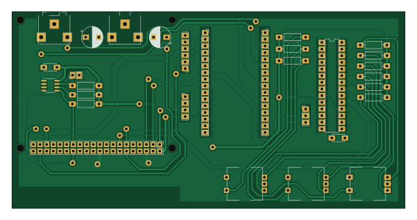
About the RTEP Pedal PCB
RTEP Pedal is an open source PCB design by Can-Bot, published on GitHub under the MIT license. It is a 2-layer board measuring 150 × 75 mm, with 30 components from 17 distinct parts.
Other key parts include the 24LC256 and MCP23017_SP. By type, the board carries 12 resistors, 8 connectors, 4 capacitors, 3 switches, 2 ICs and 1 jumper.
It belongs with the audio and dev boards & breakouts designs in this gallery.
From the project
Repository for ENG5220: Real-Time Embedded Programming - S.H.R.E.D Pedal
The Real-Time Harmoniser is a standalone real-time embedded system designed to apply audio effects (like pitch-shifting and gain distortion) to incoming audio with minimal latency. The pedal is controllable via a hardware interface and written for the ENG5220: Real-Time Embedded Programming course.
Key Features: - Modular DSP architecture with hot-swappable effect chains - Sample-by-sample processing for minimal latency - Real-time capable Harmonizer using SignalsmithStretch - Multithreaded control-safe design with atomic buffer swapping - CI-integrated Google Test unit testing - Memory-safe…
Main components on the RTEP Pedal
RTEP Pedal bill of materials (BOM)
30 components, 17 distinct parts — part numbers from the project's BOM.
| Qty | Part | Footprint | Refs |
|---|---|---|---|
| 1 | 24LC256 | SOIC-8_3.9x4.9mm_P1.27mm | U2 |
| 1 | MCP23017_SP | DIP-28_W7.62mm | U5 |
| 1 | RPi GPIO | PinHeader_2x20_P2.54mm_Vertical | J1 |
| 1 | I2C Header | PinHeader_1x03_P2.54mm_Vertical | J6 |
| 1 | PWR | PinHeader_1x04_P2.54mm_Vertical | J7 |
| 1 | I2S Header | PinHeader_1x06_P2.54mm_Vertical | J8 |
| 1 | Line In | Jack_3.5mm_CUI_SJ1-3523N_Horizontal | J9 |
| 1 | Line Out | Jack_3.5mm_CUI_SJ1-3523N_Horizontal | J10 |
| 1 | BOB21250-LEFT | PinSocket_1x16_P2.54mm_Vertical | J11 |
| 1 | BOB21250-RIGHT | PinSocket_1x16_P2.54mm_Vertical | J12 |
| 1 | Jumper_2_Open | PinHeader_1x02_P2.54mm_Vertical | JP1 |
| 3 | RotaryEncoder_Switch | RotaryEncoder_Bourns_Vertical_PEC12R-3x17F-Sxxxx | SW1, SW2, SW3 |
| 2 | 100u | CP_Radial_D8.0mm_P5.00mm | C9, C13 |
| 2 | 0.1u | C_Disc_D4.7mm_W2.5mm_P5.00mm | C40, C43 |
| 2 | 3k9 | R_Axial_DIN0207_L6.3mm_D2.5mm_P10.16mm_Horizontal | R1, R2 |
| 1 | 1k | R_Axial_DIN0207_L6.3mm_D2.5mm_P10.16mm_Horizontal | R3 |
| 9 | 10k | R_Axial_DIN0207_L6.3mm_D2.5mm_P10.16mm_Horizontal | R34, R35, R36, R37, R38, R39, R46, R47 +1 |
RTEP Pedal design files
The KiCad project lives in the Can-Bot/RTEP_Pedal repository on GitHub; these links point at the commit this page was built from.
RTEP Pedal: common questions
How big is the RTEP Pedal PCB?
The RTEP Pedal measures 150 × 75 mm, has 2 copper layers and is 1.6 mm thick.
How many components are on the RTEP Pedal?
30 components, from 17 distinct parts, with part numbers taken from the project's own BOM. The full bill of materials is listed on this page.
Where can I download the RTEP Pedal design files?
From the Can-Bot/RTEP_Pedal repository on GitHub, which has the KiCad layout, the schematic and the BOM; the links under Design files point to each one.
Can I use the RTEP Pedal design in my own project?
Yes, under the terms of its MIT license, which Can-Bot chose for the repository.
Similar boards
KLOR
GEIGEIGEIST
160.2 × 118.3 mm79 parts2LGPL-3.01.2k
134pin 7-967288-1
rusefi
139.7 × 73.7 mm38 parts2LGPL-3.01.2k
Breakout 60pin EEC-IV
139.7 × 62.2 mm15 parts2LGPL-3.01.2k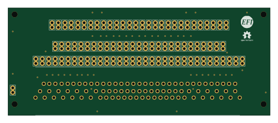
88 Pin Vag Breakout
142 × 58 mm91 parts2LGPL-3.01.2k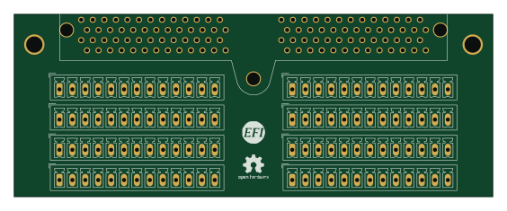
Eecv breakout
140.8 × 53.7 mm9 parts4LGPL-3.01.2k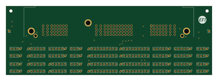
Breakout 112pin Connector
174 × 58 mm39 parts2LGPL-3.01.2k