
Test digitale

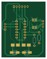
About the Test digitale PCB
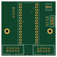
Test digitale is an open source PIC PCB design by CarloMara, published on GitHub. It is a 2-layer board measuring 40.6 × 52.1 mm, with 12 components from 8 distinct parts.
Its main chip is the PIC16F18323, from the PIC family. Other key parts include the MCP4726. By type, the board carries 4 resistors, 3 ICs, 3 connectors and 2 diodes.
From the project
So, @nicogela and I decided to build a LAB PSU, but because we're lazy people and we don't like to carry weight we're tring to unite the high efficiency of the switching topologies to the high stability and low noise of the linear ones.
So, @nicogela and I decided to build a LAB PSU, but because we're lazy people and we don't like to carry weight we're tring to unite the high efficiency of the switching topologies to the high stability and low noise of the linear ones.
Up until now we've designed the linear stage, and we added to it some DACs in oreder to controll it with a uC. The next stage in the design process will be the testing of the linear + the dacs. If everithing works we will go ahead adding to the desing the switching stage.
Main components on the Test digitale
Test digitale bill of materials (BOM)
12 components, 8 distinct parts — part numbers from the project's BOM.
| Qty | Part | Footprint | Refs |
|---|---|---|---|
| 1 | PIC16F18323 | DIP-14_W7.62mm_LongPads | U4 |
| 2 | MCP4726 | SOT-23-6_Handsoldering | U5, U6 |
| 1 | CONN_01X03 | Pin_Header_Straight_1x03 | P1 |
| 1 | UART_01X03 | Pin_Header_Straight_1x03 | P3 |
| 1 | ICSP_01X06 | Pin_Header_Straight_1x06 | P4 |
| 2 | Led_Small | SMB_Handsoldering | D13, D14 |
| 2 | R | Resistor_Horizontal_RM10mm | R1, R2 |
| 2 | 390 | Resistor_SMD+THTuniversal_0805to2512_HandSoldering | R30, R31 |
Test digitale design files
The KiCad project lives in the CarloMara/didactic-octo-PSU repository on GitHub; these links point at the commit this page was built from.
Test digitale: common questions
What microcontroller does the Test digitale use?
The Test digitale is built around the PIC16F18323, from the PIC family.
How big is the Test digitale PCB?
The Test digitale measures 40.6 × 52.1 mm, has 2 copper layers and is 1.6 mm thick.
How many components are on the Test digitale?
12 components, from 8 distinct parts, with part numbers taken from the project's own BOM. The full bill of materials is listed on this page.
Where can I download the Test digitale design files?
From the CarloMara/didactic-octo-PSU repository on GitHub, which has the KiCad layout and the BOM; the links under Design files point to each one.
Can I use the Test digitale design in my own project?
The repository has no license, so all rights stay with CarloMara. Use it as a reference, and ask the author before reusing the design.
Can I test firmware for the Test digitale without the hardware?
Yes. HardLabs builds a simulation of the board from its netlist and BOM, so you can run and debug PIC firmware against it before you order a PCB.
More boards in didactic-octo-PSU
Similar boards
 PIC
Pslab hardware
fossasia
99 × 53.3 mm187 parts4LApache-2.01.7k PIC
Lens
ervanalb
80 × 80 mm53 parts4LNo license515 PIC
Micro 8088
skiselev
152.4 × 101.6 mm71 partsGPL-3.0414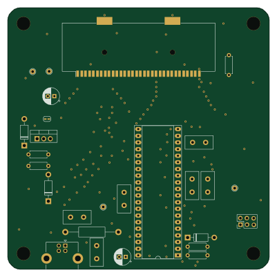 PIC
GB-CARTPP-DIY
Gekkio
100 × 100 mm22 parts2LCC-BY-4.0379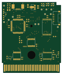 PIC
GB-LIVE32
51.4 × 61 mm46 parts4LCC-BY-4.0379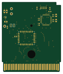 PIC
GB-CART256K-A
51.4 × 61 mm17 parts2LCC-BY-4.0379