Alimentatore

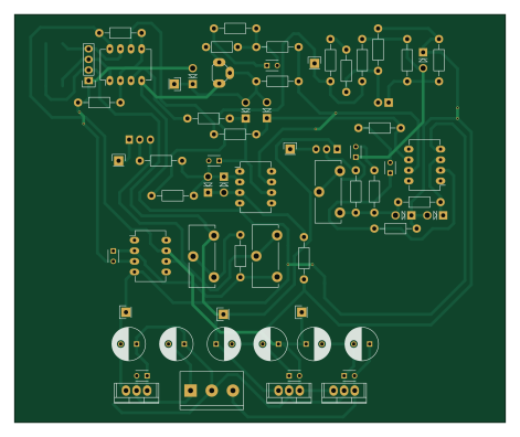
About the Alimentatore PCB
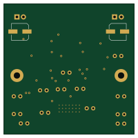
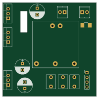
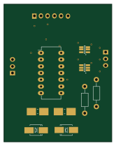
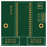
Alimentatore is an open source PCB design by CarloMara, published on GitHub. It is a 2-layer board measuring 117.6 × 97.8 mm, with 83 components from 30 distinct parts.
Other key parts include the LM741, LM393, LM7805CT, LM7812CT and LM7912CT. By type, the board carries 29 resistors, 18 capacitors, 15 connectors, 8 diodes, 7 ICs and 2 transistors.
From the project
So, @nicogela and I decided to build a LAB PSU, but because we're lazy people and we don't like to carry weight we're tring to unite the high efficiency of the switching topologies to the high stability and low noise of the linear ones.
So, @nicogela and I decided to build a LAB PSU, but because we're lazy people and we don't like to carry weight we're tring to unite the high efficiency of the switching topologies to the high stability and low noise of the linear ones.
Up until now we've designed the linear stage, and we added to it some DACs in oreder to controll it with a uC. The next stage in the design process will be the testing of the linear + the dacs. If everithing works we will go ahead adding to the desing the switching stage.
Main components on the Alimentatore
Alimentatore bill of materials (BOM)
83 components, 30 distinct parts — part numbers from the project's BOM.
| Qty | Part | Footprint | Refs |
|---|---|---|---|
| 3 | LM741 | DIP-8_W7.62mm_LongPads | U1, U2, U4 |
| 1 | LM393 | DIP-8_W7.62mm_LongPads | U3 |
| 1 | LM7805CT | TO-220 | U7 |
| 1 | LM7812CT | TO-220 | U8 |
| 1 | LM7912CT | TO-220 | U9 |
| 1 | Q_NMOS_GDS | TO-220_Neutral123_Vertical_LargePads | Q1 |
| 1 | Q_PNP_EBC | TO-92_Rugged | Q2 |
| 1 | TP6 | Pin_Header_Straight_1x01 | J1 |
| 1 | TP5 | Pin_Header_Straight_1x01 | J2 |
| 1 | TP7 | Pin_Header_Straight_1x01 | J3 |
| 1 | TP1 | Pin_Header_Straight_1x01 | J10 |
| 1 | TP2 | Pin_Header_Straight_1x01 | J11 |
| 1 | TP3 | Pin_Header_Straight_1x01 | J12 |
| 1 | LOAD_POWER_01X02 | mors_2p | P1 |
| 1 | CONN_01X03 | mors_3p | P2 |
| 1 | CONN_01X04 | Pin_Header_Straight_1x04 | P3 |
| 2 | CONN_01X03 | Pin_Header_Straight_1x03 | P4, P7 |
| 1 | CONN_01X02 | Pin_Header_Straight_1x02 | P5 |
| 1 | LOGIC_POWER_01X03 | mors_3p | P6 |
| 2 | CONN_01X01 | Pin_Header_Straight_1x01 | P8, P9 |
Show 10 more
| Qty | Part | Footprint | Refs |
|---|---|---|---|
| 3 | POT | Potentiometer_Trimmer-Piher-PT15-h5_vertical | RV1, RV2, RV3 |
| 8 | D_Small | Diode_DO-41_SOD81_Vertical_AnodeUp | D1, D2, D3, D4, D5, D6, D7, D8 |
| 1 | L_Small | Resistor_Horizontal_RM7mm | L1 |
| 2 | CP1_Small | C_Radial_D14_L31.5_P5 | C1, C6 |
| 5 | C_Small | C_Disc_D3_P2.5 | C2, C3, C4, C5, C18 |
| 2 | C_Small | C_Radial_D7.5_L11.2_P2.5 | C7, C8 |
| 6 | 470u | C_Radial_D8_L21_P3.8 | C9, C10, C11, C15, C16, C17 |
| 3 | .33u | C_Disc_D3_P2.5 | C12, C13, C14 |
| 27 | R | Resistor_Horizontal_RM10mm | R1, R2, R3, R4, R5, R6, R7, R8 +19 |
| 2 | R_Small | R_1210_HandSoldering | R28, R29 |
Alimentatore design files
The KiCad project lives in the CarloMara/didactic-octo-PSU repository on GitHub; these links point at the commit this page was built from.
Alimentatore: common questions
How big is the Alimentatore PCB?
The Alimentatore measures 117.6 × 97.8 mm, has 2 copper layers and is 1.6 mm thick.
How many components are on the Alimentatore?
83 components, from 30 distinct parts, with part numbers taken from the project's own BOM. The full bill of materials is listed on this page.
Where can I download the Alimentatore design files?
From the CarloMara/didactic-octo-PSU repository on GitHub, which has the KiCad layout and the BOM; the links under Design files point to each one.
Can I use the Alimentatore design in my own project?
The repository has no license, so all rights stay with CarloMara. Use it as a reference, and ask the author before reusing the design.