
Convertor

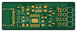
About the Convertor PCB
Convertor is an open source PCB design by Chockalingam-M, published on GitHub. It is a 2-layer board measuring 37.9 × 14.8 mm, with 27 components from 15 distinct parts.
Other key parts include the CH340K and AP2112K-3.3. By type, the board carries 8 resistors, 7 diodes, 6 capacitors, 2 ICs, 2 transistors and 2 connectors.
It belongs with the usb & debug tools designs in this gallery.
From the project
Overview This project is a USB to UART bridge designed using the CH340K USB to Serial chip. It allows for easy communication between a computer and a microcontroller through a Type-C USB connector. Ideal for programming or debugging microcontrollers like ESP32, STM32, etc.
Overview This project is a USB to UART bridge designed using the CH340K USB to Serial chip. It allows for easy communication between a computer and a microcontroller through a Type-C USB connector. Ideal for programming or debugging microcontrollers like ESP32, STM32, etc.
This USB to UART PCB was designed by carefully following Ampnics’ video and analyzing each functional block. While the current routing can be optimized further, The design serves its purpose effectively. Future revisions will focus on refining the layout, improving signal integrity, and enhancing grounding practices.
Main components on the Convertor
Convertor bill of materials (BOM)
27 components, 15 distinct parts.
| Qty | Part | Footprint | Refs |
|---|---|---|---|
| 1 | CH340K | SSOP-10-1EP_3.9x4.9mm_P1mm_EP2.1x3.3mm | U1 |
| 1 | AP2112K-3.3 | SOT-23-5 | U2 |
| 2 | SS8050 | SOT-23 | Q1, Q2 |
| 1 | USB_C_Receptacle_USB2.0_16P | HRO_TYPE-C-31-M-12 | J1 |
| 1 | Conn_02x04_Top_Bottom | PinHeader_2x04_P2.54mm_Horizontal | J2 |
| 3 | LESD5D5.0CT1G | TVS_LESD5D5.0CT1G | D1, D2, D5 |
| 3 | LED | LED_0603_1608Metric_Pad1.05x0.95mm_HandSolder | D3, D6, D7 |
| 1 | D_Schottky | D_SOD-523 | D4 |
| 2 | 100n | C_0805_2012Metric_Pad1.18x1.45mm_HandSolder | C1, C2 |
| 3 | 10u | C_0805_2012Metric_Pad1.18x1.45mm_HandSolder | C3, C4, C5 |
| 1 | 0.1u | C_0603_1608Metric_Pad1.08x0.95mm_HandSolder | C6 |
| 2 | 5.1k | R_0201_0603Metric_Pad0.64x0.40mm_HandSolder | R1, R2 |
| 3 | 220 | R_0201_0603Metric_Pad0.64x0.40mm_HandSolder | R3, R4, R5 |
| 2 | 10k | R_0201_0603Metric_Pad0.64x0.40mm_HandSolder | R6, R7 |
| 1 | 100k | R_0201_0603Metric_Pad0.64x0.40mm_HandSolder | R8 |
Convertor design files
The KiCad project lives in the Chockalingam-M/PCB-Designing repository on GitHub; these links point at the commit this page was built from.
Convertor: common questions
How big is the Convertor PCB?
The Convertor measures 37.9 × 14.8 mm, has 2 copper layers and is 1.6 mm thick.
How many components are on the Convertor?
27 components, from 15 distinct parts. The full bill of materials is listed on this page.
Where can I download the Convertor design files?
From the Chockalingam-M/PCB-Designing repository on GitHub, which has the KiCad layout and the schematic; the links under Design files point to each one.
Can I use the Convertor design in my own project?
The repository has no license, so all rights stay with Chockalingam-M. Use it as a reference, and ask the author before reusing the design.
More boards in PCB-Designing
 ESP32
ESP32ESP32
75.5 × 53.2 mm82 parts4LNo license0 STM32
STM32Bluephil STM32WB555
44.3 × 24.1 mm40 parts4LNo license0
USB C Power Supply
56 × 25.8 mm35 parts2LNo license0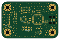
MSPM0G3507SPTR
48 × 31 mm29 parts2LNo license0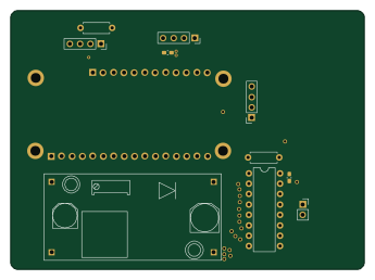 ESP32
ESP32ESP32 C6
86.1 × 63.1 mm10 parts2LNo license0
Similar boards
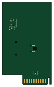
XG Station Power
osy
54.3 × 91 mm9 parts2LCC-BY-4.0703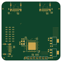
USB Hub Test
50 × 50 mm85 parts4LCC-BY-4.0703
FW-EC-DongleHiderPlus
LeoDJ
28.2 × 26.1 mm14 parts4LCERN-OHL-W-2.0490
Adapter tsop48
bbogush
48 × 33 mm3 parts2LGPL-3.0389
Adapter tsop48 solder
48 × 33 mm3 parts2LGPL-3.0389
Adapter soic8 solder
48 × 20 mm3 parts2LGPL-3.0389