
Usb c charge controller

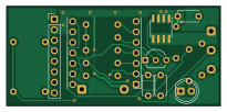
About the Usb c charge controller PCB
Usb c charge controller is an open source ESP32 PCB design by cLLeB, published on GitHub. It is a 2-layer board measuring 51.2 × 24 mm, with 20 components from 15 distinct parts.
Its main chip is the XIAO ESP32-C3, from the ESP32 family. By type, the board carries 10 resistors, 3 capacitors, 2 transistors, 2 connectors, 1 IC and 1 LED.
It belongs with the iot & wireless and power & battery designs in this gallery.
From the project
Smart USB-C charge controller on the ESP32-C3: KiCad board, C++ firmware with Wi-Fi, Bluetooth and OTA updates, Android and Windows apps
A small adapter that sits between a USB-C charger and a phone and stops charging at a battery level you choose, for example 80 %, then starts again at a lower one, for example 40 %. The phone reports its battery level over Wi-Fi, and the adapter does the switching. I designed the circuit and the board, wrote the firmware and the companion apps, and assembled, soldered and tested it in October 2026.
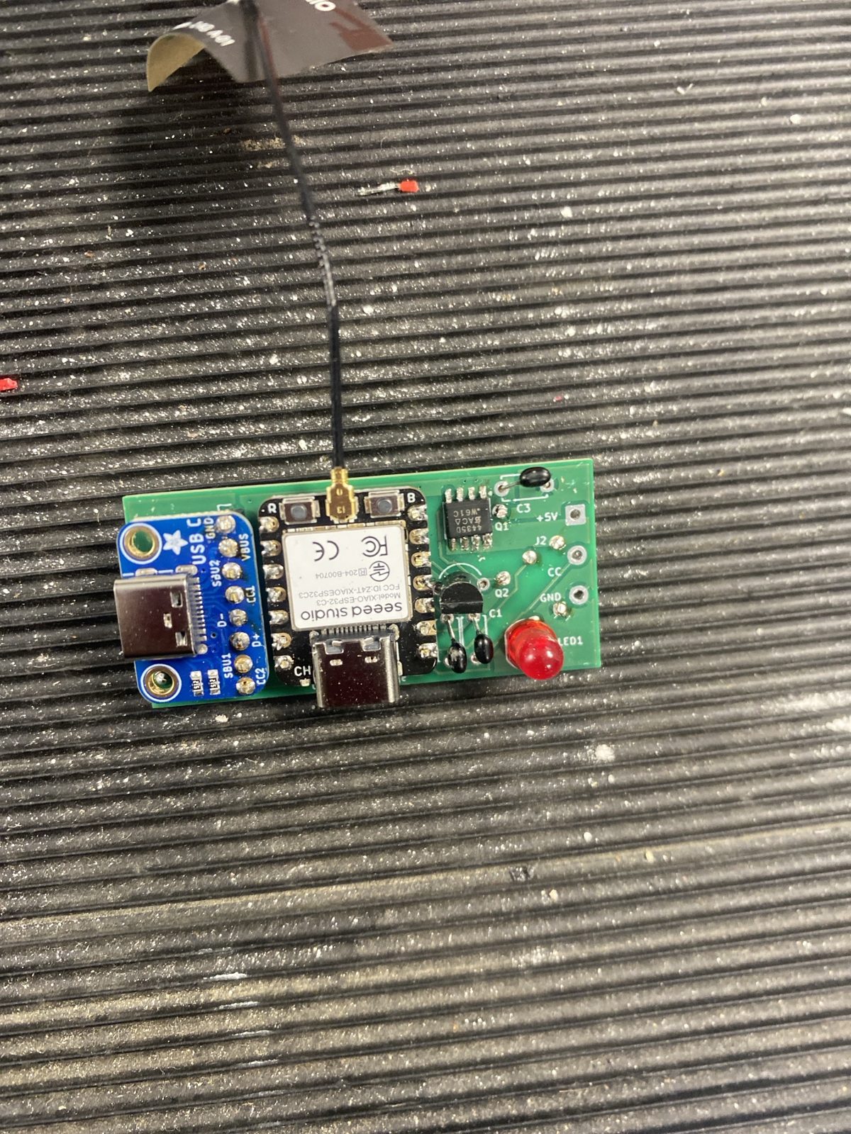
Main components on the Usb c charge controller
Usb c charge controller bill of materials (BOM)
20 components, 15 distinct parts — part numbers from the project's BOM.
| Qty | Part | Footprint | Refs |
|---|---|---|---|
| 1 | XIAO ESP32-C3 | DIP-14_W7.62mm | U1 |
| 1 | SI4435DDY | SOIC-8_3.9x4.9mm_P1.27mm | Q1 |
| 1 | 2N7000 | TO-92_Inline_Wide | Q2 |
| 1 | USB-C socket board | PinHeader_1x08_P2.54mm_Vertical | J1 |
| 1 | cable to phone | SolderWire-0.5sqmm_1x03_P4.6mm_D0.9mm_OD2.1mm | J2 |
| 1 | red 5 mm | LED_D5.0mm | LED1 |
| 1 | 1N5817 | D_DO-41_SOD81_P10.16mm_Horizontal | D1 |
| 3 | 100n | C_Disc_D4.7mm_W2.5mm_P5.00mm | C1, C2, C3 |
| 3 | 330k | R_Axial_DIN0207_L6.3mm_D2.5mm_P7.62mm_Horizontal | R1, R2, R6 |
| 1 | 33k | R_Axial_DIN0207_L6.3mm_D2.5mm_P7.62mm_Horizontal | R3 |
| 1 | 12k | R_Axial_DIN0207_L6.3mm_D2.5mm_P7.62mm_Horizontal | R4 |
| 1 | 4.7k | R_Axial_DIN0207_L6.3mm_D2.5mm_P7.62mm_Horizontal | R5 |
| 2 | 100k | R_Axial_DIN0207_L6.3mm_D2.5mm_P7.62mm_Horizontal | R7, R8 |
| 1 | 680 | R_Axial_DIN0207_L6.3mm_D2.5mm_P7.62mm_Horizontal | R9 |
| 1 | 1k | R_Axial_DIN0207_L6.3mm_D2.5mm_P7.62mm_Horizontal | R10 |
Usb c charge controller design files
The KiCad project lives in the cLLeB/usb-c-charge-controller repository on GitHub; these links point at the commit this page was built from.
- Layoutkicad/smartsocket.kicad_pcb
- Schematickicad/smartsocket.kicad_sch
- BOMkicad/bom.csv
Usb c charge controller: common questions
What microcontroller does the Usb c charge controller use?
The Usb c charge controller is built around the XIAO ESP32-C3, from the ESP32 family.
How big is the Usb c charge controller PCB?
The Usb c charge controller measures 51.2 × 24 mm, has 2 copper layers and is 1.6 mm thick.
How many components are on the Usb c charge controller?
20 components, from 15 distinct parts, with part numbers taken from the project's own BOM. The full bill of materials is listed on this page.
Where can I download the Usb c charge controller design files?
From the cLLeB/usb-c-charge-controller repository on GitHub, which has the KiCad layout, the schematic and the BOM; the links under Design files point to each one.
Can I use the Usb c charge controller design in my own project?
The repository has no license, so all rights stay with cLLeB. Use it as a reference, and ask the author before reusing the design.
Can I test firmware for the Usb c charge controller without the hardware?
Yes. HardLabs builds a simulation of the board from its netlist and BOM, so you can run and debug ESP32 firmware against it before you order a PCB.
Similar boards
 ESP32
OSO-BOOK-B1
joeycastillo
85 × 115 mm65 parts2LCC-BY-SA-4.08.1k ESP32
Powertrain
byrantech
64 × 45.4 mm171 parts4LMIT4.3k ESP32
Badge
atopile
56.3 × 39 mm239 parts4LMIT4.0k ESP32
Esp32 minimal
36.2 × 26.8 mm20 parts2LMIT4.0k ESP32
Controller
StuckAtPrototype
29 × 74 mm58 parts4LApache-2.03.8k ESP32
Racer
36 × 50.2 mm70 parts4LApache-2.03.8k