
Bus

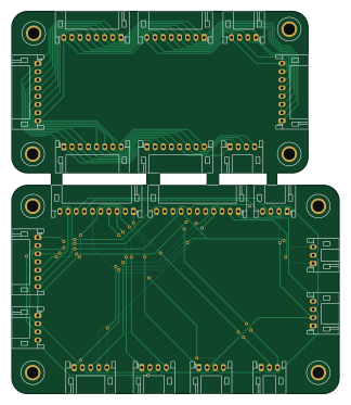
About the Bus PCB
Bus is an open source PCB design by codemonkey76, published on GitHub. It is a 2-layer board measuring 80 × 93.2 mm, with 19 components from 18 distinct parts.
From the project
DIY 8-Bit Computer, based on the design by Ben Eater
Based off schematics and design of breadboard computer by Ben Eater, available in kit form at: https://eater.net/8bit/kits
Bus bill of materials (BOM)
19 components, 18 distinct parts.
| Qty | Part | Footprint | Refs |
|---|---|---|---|
| 1 | Clock | JST_PH_S3B-PH-K_1x03_P2.00mm_Horizontal | J1 |
| 1 | Control Logic Flags #1 | JST_PH_S10B-PH-K_1x10_P2.00mm_Horizontal | J2 |
| 1 | Output Register | JST_PH_S8B-PH-K_1x08_P2.00mm_Horizontal | J3 |
| 1 | Output Register | JST_PH_S3B-PH-K_1x03_P2.00mm_Horizontal | J5 |
| 1 | Instruction Register | JST_PH_S8B-PH-K_1x08_P2.00mm_Horizontal | J8 |
| 1 | Control Logic Flags #2 | JST_PH_S11B-PH-K_1x11_P2.00mm_Horizontal | J9 |
| 1 | Instruction Register | JST_PH_S4B-PH-K_1x04_P2.00mm_Horizontal | J12 |
| 1 | A Register | JST_PH_S8B-PH-K_1x08_P2.00mm_Horizontal | J13 |
| 1 | A Register | JST_PH_S4B-PH-K_1x04_P2.00mm_Horizontal | J17 |
| 2 | MAR | JST_PH_S4B-PH-K_1x04_P2.00mm_Horizontal | J18, J19 |
| 1 | B Register | JST_PH_S8B-PH-K_1x08_P2.00mm_Horizontal | J20 |
| 1 | B Register | JST_PH_S4B-PH-K_1x04_P2.00mm_Horizontal | J25 |
| 1 | Memory | JST_PH_S8B-PH-K_1x08_P2.00mm_Horizontal | J26 |
| 1 | Memory | JST_PH_S4B-PH-K_1x04_P2.00mm_Horizontal | J29 |
| 1 | Arithmetic Logic Unit | JST_PH_S7B-PH-K_1x07_P2.00mm_Horizontal | J30 |
| 1 | Arithmetic Logic Unit | JST_PH_S8B-PH-K_1x08_P2.00mm_Horizontal | J31 |
| 1 | Program Counter | JST_PH_S4B-PH-K_1x04_P2.00mm_Horizontal | J32 |
| 1 | Program Counter | JST_PH_S5B-PH-K_1x05_P2.00mm_Horizontal | J36 |
Bus design files
The KiCad project lives in the codemonkey76/DIY-8-Bit-Computer repository on GitHub; these links point at the commit this page was built from.
- LayoutBus/Bus.kicad_pcb
Bus: common questions
How big is the Bus PCB?
The Bus measures 80 × 93.2 mm, has 2 copper layers and is 1.6 mm thick.
How many components are on the Bus?
19 components, from 18 distinct parts. The full bill of materials is listed on this page.
Where can I download the Bus design files?
From the codemonkey76/DIY-8-Bit-Computer repository on GitHub, which has the KiCad layout; the links under Design files point to each one.
Can I use the Bus design in my own project?
The repository has no license, so all rights stay with codemonkey76. Use it as a reference, and ask the author before reusing the design.
More boards in DIY-8-Bit-Computer
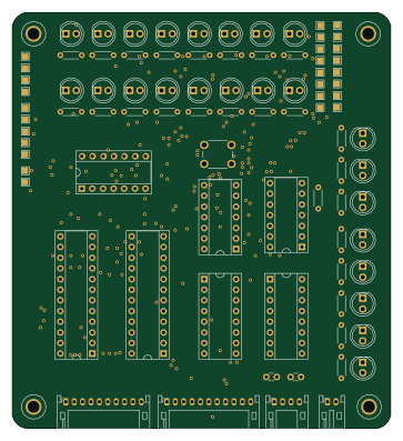
Control logic
90.2 × 99.1 mm63 parts2LNo license0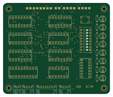
Memory
95.3 × 81.3 mm33 parts2LNo license0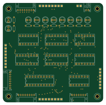
Alu
90.2 × 88.9 mm33 parts2LNo license0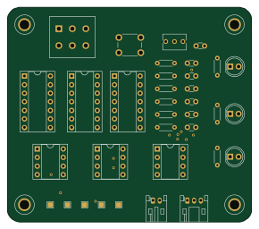
DIY 8-Bit Computer - Clock
72.4 × 63.5 mm30 parts2LNo license0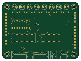
Register a
78.7 × 58.4 mm24 parts2LNo license0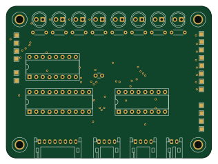
Instruction register
78.7 × 58.4 mm24 parts2LNo license0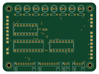
Register b
78.7 × 58.4 mm24 parts2LNo license0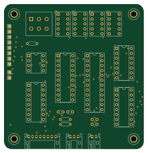
Output register
72.4 × 74.9 mm21 parts2LNo license0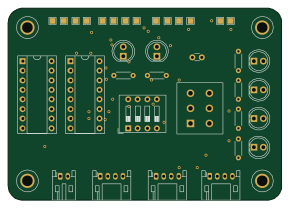
Address register
72.4 × 50.8 mm21 parts2LNo license0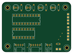
Program counter
63.5 × 45.7 mm14 parts2LNo license0