
Enhanced-EPROM-Programmer

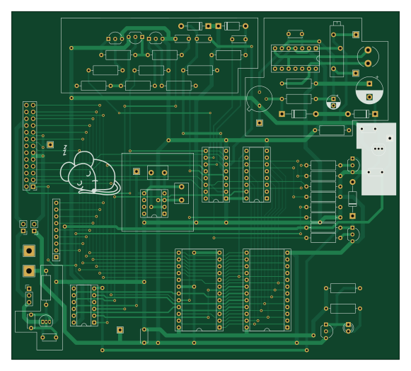
About the Enhanced-EPROM-Programmer PCB
Enhanced-EPROM-Programmer is an open source PCB design by codesqueak, published on GitHub under the CERN-OHL-S-2.0 license. It is a 2-layer board measuring 145 × 130 mm, with 74 components from 54 distinct parts.
Other key parts include the 4049, TL497_Fixed, LM78L12_TO92, 4040 and LMC7660. By type, the board carries 24 resistors, 11 capacitors, 7 test points, 6 diodes, 5 ICs and 2 jumpers.
It belongs with the usb & debug tools and retro computing designs in this gallery.
From the project
Enhanced 2708 / 2716 EPROM Programmer using single 5V supply / PIO Port Attached
This card has been designed to be a functional replacement for the Bits & PCs Nascom EPROM Programmer. It is fully compatible with the existing software.
The card is a completely new implementation of the design with a number of improvements over the original:
Single power source requirement (+5V only) Completely new track layout All components are readily available from commercial component suppliers (..and eBay!) Single power switch, EPROM selection via standard 12 PIN DIL socket mounted switch LED power indicator Power test points * Adjustable 25V feed for 2708's
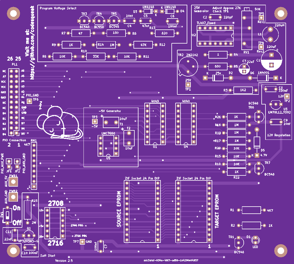
Main components on the Enhanced-EPROM-Programmer
Enhanced-EPROM-Programmer bill of materials (BOM)
74 components, 54 distinct parts.
| Qty | Part | Footprint | Refs |
|---|---|---|---|
| 1 | 4049 | DIP-16_W7.62mm_Socket | U1 |
| 1 | TL497_Fixed | DIP-14_W7.62mm_Socket | U2 |
| 1 | LM78L12_TO92 | TO-92_Inline | U3 |
| 1 | 4040 | DIP-16_W7.62mm_Socket | U4 |
| 1 | LMC7660 | DIP-8_W7.62mm_Socket | U5 |
| 1 | VP3203N3-G | TO-92L_Inline | Q1 |
| 1 | PIO_AUX_PWR | PinHeader_1x02_P2.54mm_Vertical | JP1 |
| 1 | PIO_AUX_GND | PinHeader_1x02_P2.54mm_Vertical | JP2 |
| 1 | PIO Connection | PinHeader_2x13_P2.54mm_Vertical | PL1 |
| 1 | AUX_5V | TestPoint_THTPad_4.0x4.0mm_Drill2.0mm | PWR1 |
| 1 | AUX_GND | TestPoint_THTPad_4.0x4.0mm_Drill2.0mm | PWR2 |
| 1 | 50K | Potentiometer_Vishay_43_Horizontal | RV1 |
| 2 | ZIF Socket 24 Pin DIP | DIP-24_W15.24mm_Socket | SKT1-ZIF-Donor_1, SKT2-ZIF-Target_1 |
| 1 | SW_SPDT | PinHeader_1x03_P2.54mm_Vertical | SW1 |
| 1 | 4PDT Switch | DIP-12_W7.62mm_Socket | SW_2708_2716_1 |
| 2 | 10uF | C_Disc_D7.5mm_W5.0mm_P5.00mm | T1, T2 |
| 1 | 25V | TestPoint_THTPad_2.0x2.0mm_Drill1.0mm | TP1 |
| 1 | 12V | TestPoint_THTPad_2.0x2.0mm_Drill1.0mm | TP2 |
| 1 | -5V | TestPoint_THTPad_2.0x2.0mm_Drill1.0mm | TP3 |
| 1 | Res2 | TestPoint_THTPad_2.0x2.0mm_Drill1.0mm | TP4 |
Show 34 more
| Qty | Part | Footprint | Refs |
|---|---|---|---|
| 1 | Res1 | TestPoint_THTPad_2.0x2.0mm_Drill1.0mm | TP5 |
| 1 | PIO_GND | TestPoint_THTPad_2.0x2.0mm_Drill1.0mm | TP6 |
| 1 | GND | TestPoint_THTPad_2.0x2.0mm_Drill1.0mm | TP7 |
| 5 | BC548 | TO-92_Inline_Wide | TR1, TR3, TR5, TR6, TR7 |
| 1 | 2N2102 | TO-39-3 | TR2 |
| 1 | BC558 | TO-92_Inline_Wide | TR4 |
| 1 | LED | LED_D3.0mm | D1 |
| 1 | 25v | D_DO-41_SOD81_P12.70mm_Horizontal | D2 |
| 2 | 1N4148 | D_DO-41_SOD81_P10.16mm_Horizontal | D3, D4 |
| 1 | 4.7V | D_DO-41_SOD81_P12.70mm_Horizontal | D5 |
| 1 | 1N4001 | D_DO-41_SOD81_P10.16mm_Horizontal | D6 |
| 1 | 220uH | L_Radial_D7.8mm_P5.00mm_Fastron_07HCP | L1 |
| 1 | 120uF | CP_Radial_D10.0mm_P5.00mm | C1 |
| 1 | 220pF | C_Disc_D5.0mm_W2.5mm_P5.00mm | C2 |
| 1 | 22uF | CP_Radial_D5.0mm_P2.50mm | C3 |
| 2 | 10nf | C_Disc_D5.0mm_W2.5mm_P5.00mm | C4, C9 |
| 1 | 47nf | C_Disc_D5.0mm_W2.5mm_P5.00mm | C5 |
| 3 | 100nf | C_Disc_D5.0mm_W2.5mm_P5.00mm | C6, C7, C10 |
| 1 | 330nF | C_Disc_D5.0mm_W2.5mm_P5.00mm | C8 |
| 1 | 22nF | C_Disc_D5.0mm_W2.5mm_P5.00mm | C11 |
| 1 | 4K7 | R_Axial_DIN0309_L9.0mm_D3.2mm_P12.70mm_Horizontal | R1 |
| 4 | 1K | R_Axial_DIN0309_L9.0mm_D3.2mm_P12.70mm_Horizontal | R2, R9, R21, R22 |
| 1 | 1K2 | R_Axial_DIN0309_L9.0mm_D3.2mm_P12.70mm_Horizontal | R3 |
| 1 | 1 | R_Axial_DIN0309_L9.0mm_D3.2mm_P12.70mm_Horizontal | R4 |
| 1 | 680 | R_Axial_DIN0309_L9.0mm_D3.2mm_P12.70mm_Horizontal | R5 |
| 1 | 180 | R_Axial_DIN0309_L9.0mm_D3.2mm_P12.70mm_Horizontal | R6 |
| 1 | 47 | R_Axial_DIN0309_L9.0mm_D3.2mm_P12.70mm_Horizontal | R7 |
| 5 | 10K | R_Axial_DIN0309_L9.0mm_D3.2mm_P12.70mm_Horizontal | R8, R11, R15, R18, R20 |
| 1 | 33K | R_Axial_DIN0309_L9.0mm_D3.2mm_P12.70mm_Horizontal | R10 |
| 1 | 47K | R_Axial_DIN0309_L9.0mm_D3.2mm_P12.70mm_Horizontal | R12 |
| 1 | 820K | R_Axial_DIN0309_L9.0mm_D3.2mm_P12.70mm_Horizontal | R13 |
| 4 | 1M | R_Axial_DIN0309_L9.0mm_D3.2mm_P12.70mm_Horizontal | R14, R16, R17, R19 |
| 1 | 2M | R_Axial_DIN0309_L9.0mm_D3.2mm_P12.70mm_Horizontal | R23 |
| 1 | 4K7 | R_Array_SIP9 | RN1 |
Enhanced-EPROM-Programmer design files
The KiCad project lives in the codesqueak/Enhanced-EPROM-Programmer repository on GitHub; these links point at the commit this page was built from.
- Layoutkicad/80bus.kicad_pcb
- Schematickicad/80bus.kicad_sch
Enhanced-EPROM-Programmer: common questions
How big is the Enhanced-EPROM-Programmer PCB?
The Enhanced-EPROM-Programmer measures 145 × 130 mm, has 2 copper layers and is 1.6 mm thick.
How many components are on the Enhanced-EPROM-Programmer?
74 components, from 54 distinct parts. The full bill of materials is listed on this page.
Where can I download the Enhanced-EPROM-Programmer design files?
From the codesqueak/Enhanced-EPROM-Programmer repository on GitHub, which has the KiCad layout and the schematic; the links under Design files point to each one.
Can I use the Enhanced-EPROM-Programmer design in my own project?
Yes, under the terms of its CERN-OHL-S-2.0 license, which codesqueak chose for the repository.
Similar boards
Expansion Card Retrofit
FrameworkComputer
24 × 27.3 mm5 parts2LCC-BY-4.01.1k
Rgb to hdmi
hoglet67
77 × 97 mm67 parts2LGPL-3.01.0k
Buffer
53.9 × 23.2 mm13 parts2LGPL-3.01.0k
X1
121.9 × 81.3 mm51 parts2LGPL-3.01.0k
Amiga External
21.9 × 76.7 mm6 parts2LGPL-3.01.0k
Videoslotadapter
152 × 57.6 mm13 parts2LGPL-3.01.0k