
BE Project

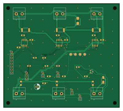
About the BE Project PCB
BE Project is an open source ESP32 PCB design by D7790, published on GitHub. It is a 4-layer board measuring 100 × 90 mm, with 42 components from 29 distinct parts.
Its main chip is the ESP32_SIGNALS, from the ESP32 family. Other key parts include the INA219AIDR. By type, the board carries 11 connectors, 11 capacitors, 10 resistors, 3 ICs, 3 fuses and 2 diodes.
It belongs with the power & battery designs in this gallery.
From the project
Battery-mounted, battery-powered monitoring and advice using remaining-energy/runtime estimates and known AC/DC load signatures.
Battery-mounted, battery-powered monitoring and advice using remaining-energy/runtime estimates and known AC/DC load signatures.
Current scope — clarified 3 October 2026: Start with the battery-centred scope. WattSense mounts near the battery and runs from a regulated battery supply. It estimates remaining charge, usable energy and runtime, then recommends which optional loads to turn off using known signatures and user priorities. Solar or a compatible AC-to-DC charger charges the battery; DC loads use converters and AC loads use an inverter. Random Forest is a candidate to compare with a…
Main components on the BE Project
BE Project bill of materials (BOM)
42 components, 29 distinct parts — part numbers from the project's BOM.
| Qty | Part | Footprint | Refs |
|---|---|---|---|
| 3 | INA219AIDR | SOIC-8_3.9x4.9mm_P1.27mm | U1, U2, U3 |
| 1 | AO3400A | SOT-23 | Q1 |
| 1 | BATTERY_AFTER_FUSE | TerminalBlock_Phoenix_MKDS-1,5-2-5.08_1x02_P5.08mm_Horizontal | J1 |
| 1 | CHARGER_BAT_PORT | TerminalBlock_Phoenix_MKDS-1,5-2-5.08_1x02_P5.08mm_Horizontal | J2 |
| 1 | TO_BUCK_INPUT | TerminalBlock_Phoenix_MKDS-1,5-2-5.08_1x02_P5.08mm_Horizontal | J3 |
| 1 | FROM_BUCK_5V | TerminalBlock_Phoenix_MKDS-1,5-2-5.08_1x02_P5.08mm_Horizontal | J4 |
| 1 | ESSENTIAL_LAMP | TerminalBlock_Phoenix_MKDS-1,5-2-5.08_1x02_P5.08mm_Horizontal | J5 |
| 1 | OPTIONAL_FAN | TerminalBlock_Phoenix_MKDS-1,5-2-5.08_1x02_P5.08mm_Horizontal | J6 |
| 1 | ESP32_SIGNALS | PinHeader_1x08_P2.54mm_Vertical | J7 |
| 1 | DS18B20 | PinHeader_1x03_P2.54mm_Vertical | J8 |
| 1 | LOAD_BUTTON | PinHeader_1x02_P2.54mm_Vertical | J9 |
| 1 | FULL_CONFIRM | PinHeader_1x02_P2.54mm_Vertical | J10 |
| 1 | ESP32_5V_OPTION | PinHeader_1x02_P2.54mm_Vertical | J11 |
| 1 | 0466002.NR 2A 63V FAST | Fuse_1206_3216Metric_Pad1.42x1.75mm_HandSolder | F1 |
| 2 | 0466001.NR 1A 63V FAST | Fuse_1206_3216Metric_Pad1.42x1.75mm_HandSolder | F2, F3 |
| 1 | REMOVE_FOR_USB | PinHeader_1x02_P2.54mm_Vertical | JP1 |
| 1 | SS14-E3/61T SS14 | D_SMA | D1 |
| 1 | SMBJ15A-E3/52 SMBJ15A | D_SMB | D2 |
| 3 | GRM21BR71C104KA01L 100n 16V X7R | C_0805_2012Metric_Pad1.18x1.45mm_HandSolder | C1, C2, C3 |
| 1 | 1u 16V X7R | C_0805_2012Metric_Pad1.18x1.45mm_HandSolder | C4 |
Show 9 more
| Qty | Part | Footprint | Refs |
|---|---|---|---|
| 3 | 100n 16V X7R | C_0805_2012Metric_Pad1.18x1.45mm_HandSolder | C5, C6, C7 |
| 3 | GRM21BR71H103KA01L 10n 50V X7R | C_0805_2012Metric_Pad1.18x1.45mm_HandSolder | C8, C9, C10 |
| 1 | 47u 25V | CP_Radial_D5.0mm_P2.00mm | C11 |
| 3 | WSL2512R1000FEA 0.1R 1% 1W | R_2512_6332Metric_Pad1.40x3.35mm_HandSolder | R1, R2, R3 |
| 2 | RC0805FR-072K2L 2.2k | R_0805_2012Metric_Pad1.20x1.40mm_HandSolder | R4, R5 |
| 1 | RC0805FR-074K7L 4.7k | R_0805_2012Metric_Pad1.20x1.40mm_HandSolder | R6 |
| 1 | RC0805FR-07330RL 330R | R_0805_2012Metric_Pad1.20x1.40mm_HandSolder | R7 |
| 1 | RC0805FR-0747KL 47k | R_0805_2012Metric_Pad1.20x1.40mm_HandSolder | R8 |
| 2 | RC0805FR-0710KL 10k | R_0805_2012Metric_Pad1.20x1.40mm_HandSolder | R9, R10 |
BE Project design files
The KiCad project lives in the D7790/BE_Project repository on GitHub; these links point at the commit this page was built from.
BE Project: common questions
What microcontroller does the BE Project use?
The BE Project is built around the ESP32_SIGNALS, from the ESP32 family.
How big is the BE Project PCB?
The BE Project measures 100 × 90 mm, has 4 copper layers and is 1.6 mm thick.
How many components are on the BE Project?
42 components, from 29 distinct parts, with part numbers taken from the project's own BOM. The full bill of materials is listed on this page.
Where can I download the BE Project design files?
From the D7790/BE_Project repository on GitHub, which has the KiCad layout, the schematic and the BOM; the links under Design files point to each one.
Can I use the BE Project design in my own project?
The repository has no license, so all rights stay with D7790. Use it as a reference, and ask the author before reusing the design.
Can I test firmware for the BE Project without the hardware?
Yes. HardLabs builds a simulation of the board from its netlist and BOM, so you can run and debug ESP32 firmware against it before you order a PCB.
Similar boards
 ESP32
OSO-BOOK-B1
joeycastillo
85 × 115 mm65 parts2LCC-BY-SA-4.08.1k ESP32
Powertrain
byrantech
64 × 45.4 mm171 parts4LMIT4.3k ESP32
Badge
atopile
56.3 × 39 mm239 parts4LMIT4.0k ESP32
Esp32 minimal
36.2 × 26.8 mm20 parts2LMIT4.0k ESP32
Controller
StuckAtPrototype
29 × 74 mm58 parts4LApache-2.03.8k ESP32
Racer
36 × 50.2 mm70 parts4LApache-2.03.8k