
14 open source boards using the INA219AIDR
Real designs built with the INA219AIDR, from public GitHub projects: a quick way to see how others power, decouple and connect it. Each board comes with its KiCad files, full parts list and a render — and you can simulate its firmware on HardLabs.
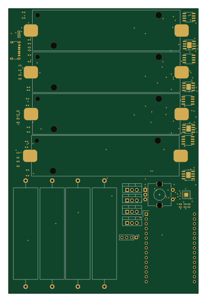 ESP32
18650-Tester
Studented0
100 × 150 mm65 parts2LMIT4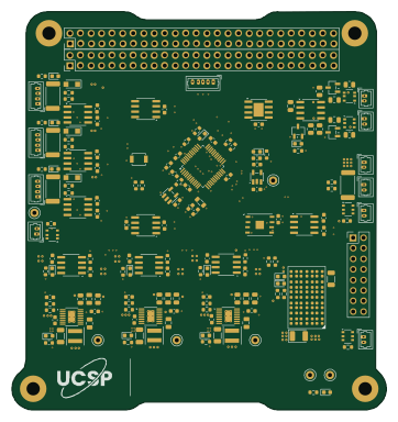 STM32
PowerDistribution
UChicago-Space-Program
90.2 × 96 mm183 parts4LNo license1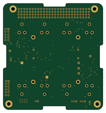 STM32
Battery board v2
queens-satellite-team
90.2 × 96 mm119 parts4LNo license1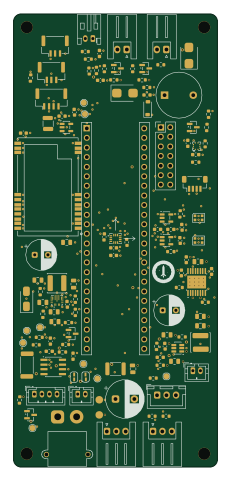 NXP
Kartonaut
Jan-Philipp-Munsch
54 × 120 mm118 parts4LMIT0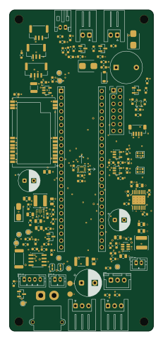 NXP
Mission space
54 × 120 mm118 parts4LMIT0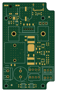
Camera-Cooler
lukaslibar
45 × 75 mm106 parts4LCustom license0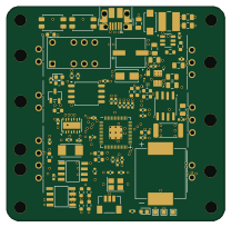 RP2040/RP2350
ThumbMuncher
Alsa2
52 × 51 mm82 parts4LNo license0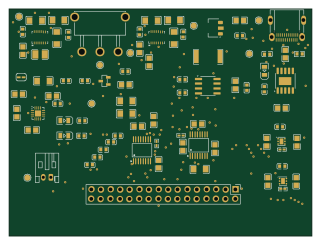
EEE3088F-MicroMouse-Power-Board-Group-21
MikeLight11
80 × 60 mm78 parts2LNo license0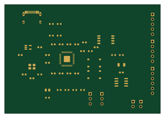 RP2040/RP2350
Helios cad forge
draarivpatel-ui
80 × 56 mm48 parts2LMIT0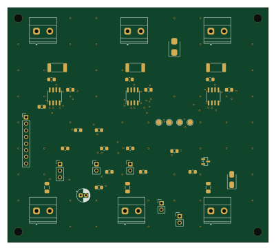 ESP32
BE Project
D7790
100 × 90 mm42 parts4LNo license0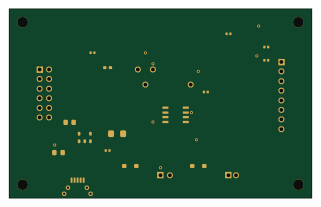
Aegis mtstdp
krishharma
80 × 50 mm18 parts2LMIT0- schematic only · 20 partsSTM32
AESH2026
iamanimeshshukl
20 partsNo license0 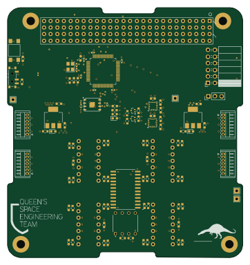 STM32
MC SunSensor
90.2 × 95.9 mm104 parts4LNo license1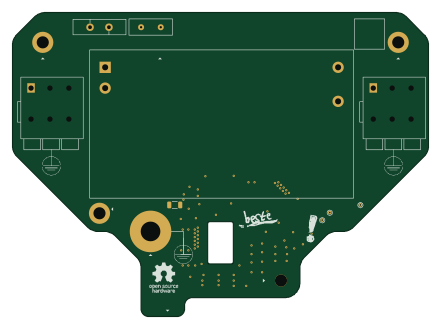
BesteLampe! ABL Power Module
lenaschimmel
110 × 80.4 mm26 parts2LNo license18
How designs wire the INA219AIDR
Read from the KiCad layouts of 12 open source designs, one per repository: what each pin of the INA219AIDR connects to, and the resistors, capacitors and other passives placed on it.
- The A1 pin is tied to GND on 11 of 12 designs.
- The A0 pin is tied to GND on 10 of 12 designs.
- The SDA pin has a pull-up to 3.3V on 6 of 12 designs, most often 4.7 kΩ (then 2.2 kΩ).
- The SCL pin has a pull-up to 3.3V on 6 of 12 designs, most often 4.7 kΩ (then 2.2 kΩ).
| Pin | Connected to | Parts on the pin |
|---|---|---|
| A1pin 1 | Connected to: GND 92% | — |
| A0pin 2 | Connected to: GND 83% | — |
| SDApin 3 | Connected to: A connector 58%, the microcontroller 42% |
|
| SCLpin 4 | Connected to: A connector 58%, the microcontroller 42% |
|
| VSpin 5 | Connected to: 3.3V 67% · GND 17% · a signal 17% |
|
| GNDpin 6 | Connected to: GND 92% | — |
| IN-pin 7 | Connected to: Signal 58% · VBAT_MEAS 33% |
|
| IN+pin 8 | Connected to: A connector 33% · VBAT_PROT 33% |
|
Connections count pins, parts count designs; values in brackets are how many parts had that value. Designs read include BesteLampe! ABL Power Module by lenaschimmel, 18650-Tester by Studented0, Battery board v2 by queens-satellite-team and PowerDistribution by UChicago-Space-Program.
The INA219AIDR in open source designs
The gallery holds 14 open source boards using the INA219AIDR from 13 GitHub repositories; a typical one measures about 80 × 90 mm and carries around 80 components.
62% use four copper layers or more, and 36% carry an open source license.
The most starred is BesteLampe! ABL Power Module by lenaschimmel.
Parts used alongside the INA219AIDR
Microcontrollers on boards using the INA219AIDR
What boards using the INA219AIDR are built for
INA219AIDR: common questions
Where can I find a INA219AIDR reference design?
Each of the 14 boards on this page is a real design using the INA219AIDR. Open one to see how it is wired up, with the full BOM, a render of the layout and links to its KiCad files.
How is the INA219AIDR A1 pin connected?
The A1 pin is tied to GND on 11 of 12 designs. Counted from the KiCad layouts of 12 open source designs using the INA219AIDR.
How is the INA219AIDR A0 pin connected?
The A0 pin is tied to GND on 10 of 12 designs. Counted from the KiCad layouts of 12 open source designs using the INA219AIDR.
What pull-up resistor is used on the INA219AIDR SDA pin?
The SDA pin has a pull-up to 3.3V on 6 of 12 designs, most often 4.7 kΩ (then 2.2 kΩ). Counted from the KiCad layouts of 12 open source designs using the INA219AIDR.
What parts are used alongside the INA219AIDR?
The AP2112K-3.3TRG1, 74AHCT1G125, BMP390, DRV8833PWPR and E22-400T22S appear in the most repositories here.
Which microcontrollers do boards using the INA219AIDR use?
Most are built on STM32 (4), ESP32 (2), NXP (2) and RP2040/RP2350 (2).
How big is a typical board using the INA219AIDR?
The median is 80 × 90 mm, and 38% are two-layer designs.
What is the most popular open source board using the INA219AIDR?
By GitHub stars, BesteLampe! ABL Power Module by lenaschimmel, with 18 stars.
Can I simulate one of these boards using the INA219AIDR before building it?
Yes. HardLabs turns a board's netlist and BOM into a working simulation, so you can boot and test firmware against it with no hardware on your desk.