
TubeAmp

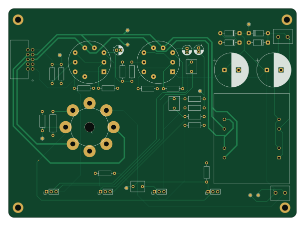
About the TubeAmp PCB
TubeAmp is an open source PCB design by davw4453, published on GitHub under the CC-BY-NC-4.0 license. It is a 2-layer board measuring 152.4 × 110.6 mm, with 39 components from 18 distinct parts.
Other key parts include the ECC88 and 7591s. By type, the board carries 16 resistors, 8 capacitors, 4 diodes, 3 ICs, 3 connectors and 1 transistor.
It belongs with the audio designs in this gallery.
From the project
This is a vacuum tube amplifier with modular input modules to provide for different audio source methods. This project was designed for my captsone project at CCSU.
1. Have the mainboard and aux input module manufactured at your fab house of choice (JLCPCB, OshPark, etc.).
Mainboard Gerbers: EDAFiles/KiCADSCH/tubeAmp/gerbers/ Aux Module Gerbers: EDAFiles/KiCADSCH/auxModule/auxModule/gerbers/
2. Assemble the PCBs according to the component designators in the BOM: BOM/tubeAmp_BOM.ods
3. 3D print the case and lid. You can load tubecase.stl and tubecase-lid.3MF into a slicer and print in the material of choice. (I used BambuStudio and printed in clear PLA). The .3mf files are the BambuStudio project files. The .sldprt and .slddrw files are Solidworks CAD…
Main components on the TubeAmp
TubeAmp bill of materials (BOM)
39 components, 18 distinct parts.
| Qty | Part | Footprint | Refs |
|---|---|---|---|
| 2 | ECC88 | Valve_Noval_P | U1, U2 |
| 1 | 7591s | OCTAL_CENTERHOLE | U3 |
| 1 | VPP12-800 | TRANS_VPP12-800_TRM | Q1 |
| 2 | 691137710002 | 691137710002-2screw | J1, J3 |
| 1 | 702471054 | CONN_7024710xx_10pos | J2 |
| 4 | 10K, 1/4W | PinHeader_1x03_P2.54mm_Vertical | RV1, RV2, RV3, RV4 |
| 4 | 1N4004 | D_DO-41_SOD81_P10.16mm_Horizontal | D1, D2, D3, D4 |
| 3 | 1u, 100V | CP_Radial_D5.0mm_P2.00mm | C1, C2, C3 |
| 1 | 200p, 50V | C_Rect_L7.2mm_W5.5mm_P5.00mm_FKS2_FKP2_MKS2_MKP2 | C4 |
| 1 | 10n, 50V | C_Rect_L7.2mm_W5.5mm_P5.00mm_FKS2_FKP2_MKS2_MKP2 | C5 |
| 1 | 220n, 50V | C_Rect_L7.2mm_W5.5mm_P5.00mm_FKS2_FKP2_MKS2_MKP2 | C6 |
| 2 | 470u, 200V | CP_Radial_D18.0mm_P7.50mm | C7, C8 |
| 6 | 330, 1/4W | R_Axial_DIN0207_L6.3mm_D2.5mm_P10.16mm_Horizontal | R1, R2, R3, R6, R7, R8 |
| 2 | 100K, 1/4W | R_Axial_DIN0207_L6.3mm_D2.5mm_P10.16mm_Horizontal | R4, R12 |
| 2 | 560K, 1/4W | R_Axial_DIN0207_L6.3mm_D2.5mm_P10.16mm_Horizontal | R5, R15 |
| 3 | 2.2K, 1/4W | R_Axial_DIN0207_L6.3mm_D2.5mm_P10.16mm_Horizontal | R9, R10, R11 |
| 2 | 1K, 1/4W | R_Axial_DIN0207_L6.3mm_D2.5mm_P10.16mm_Horizontal | R13, R14 |
| 1 | 450, 1/2W | R_Axial_DIN0309_L9.0mm_D3.2mm_P12.70mm_Horizontal | R16 |
TubeAmp design files
The KiCad project lives in the davw4453/Tube-Amplifier-Project repository on GitHub; these links point at the commit this page was built from.
TubeAmp: common questions
How big is the TubeAmp PCB?
The TubeAmp measures 152.4 × 110.6 mm, has 2 copper layers and is 1.6 mm thick.
How many components are on the TubeAmp?
39 components, from 18 distinct parts. The full bill of materials is listed on this page.
Where can I download the TubeAmp design files?
From the davw4453/Tube-Amplifier-Project repository on GitHub, which has the KiCad layout and the schematic; the links under Design files point to each one.
Can I use the TubeAmp design in my own project?
It is published under CC-BY-NC-4.0, which limits how it may be reused; read the license before building on it.
More boards in Tube-Amplifier-Project
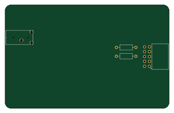
Similar boards
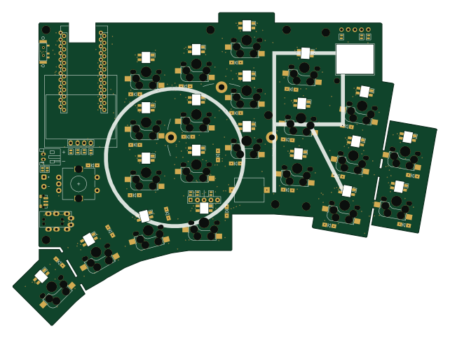
KLOR
GEIGEIGEIST
160.2 × 118.3 mm79 parts2LGPL-3.01.2k
ButtonsLEDs
shanteacontrols
390 × 37 mm82 parts2LApache-2.0956
USB
52 × 12.6 mm6 parts2LApache-2.0956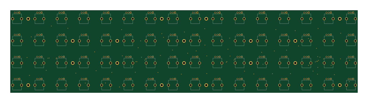
Pots
390 × 93 mm75 parts2LApache-2.0956
PicoGUS Hand386
polpo
29.2 × 75.2 mm43 parts4LGPL-2.0800
Snark barker
schlae
231.1 × 106.7 mm193 parts2LNo license687