
Defcon27-Badge


About the Defcon27-Badge PCB
Defcon27-Badge is an open source Nordic nRF PCB design by dczia, published on GitHub. It is a 2-layer board measuring 3.2 × 3.2 mm, with 90 components from 45 distinct parts.
Its main chip is the BMD-340, from the Nordic nRF family. Other key parts include the XC6221A282MR-G, PAM2305DABADJ, VL6180X and LM4861. By type, the board carries 31 resistors, 18 capacitors, 13 diodes, 7 connectors, 7 switches and 6 ICs.
It belongs with the audio, wearables and displays & leds designs in this gallery.
From the project
DCZia Defcon27 Laser Theremin Synthesizer Badge - 2019
This year we wanted to do something different. Our idea is to use two laser time of flight sensors that can measure the distance of your hands moving around infront of the badge to control a synthesizer to create a laser theremin.
- 64Mhz Arm CortexM4F with Bluetooth 5 - 5 Mechanical Clicky Low Profile Key Switches - Rotary Encoder with Click Button - OLED Display - Onboard Speaker and Amplifier! - 1/8" Headphone Out Audio Jack - SD Card Storage - RGB Leds - 2 SAO / "Shitty Add-On" Connectors

Main components on the Defcon27-Badge
Defcon27-Badge bill of materials (BOM)
90 components, 45 distinct parts — part numbers from the project's BOM.
| Qty | Part | Footprint | Refs |
|---|---|---|---|
| 1 | XC6221A282MR-G | SOT-23-5 | U1 |
| 1 | PAM2305DABADJ | SOT-23-5 | U2 |
| 1 | BMD-340 | RIGADO_BMD-340 | U3 |
| 2 | VL6180X | VL6180X | U4, U5 |
| 1 | LM4861 | SOIC-8_3.9x4.9mm_P1.27mm | U6 |
| 1 | NCE3407A FDN360P | SOT-23 | Q1 |
| 2 | BSS138 | SOT-323_SC-70 | Q2, Q3 |
| 2 | Badgelife_sao_connector_v169bis | Badgelife-Shitty-v1.69bis | X1, X2 |
| 1 | JTAG | PinHeader_2x05_P1.27mm_Vertical_Sneaky | J1 |
| 1 | TF-01 Micro_SD_Card_SPI | MicroSD-Socket-Seeed-320090008 | J2 |
| 1 | USB_B_Micro | MICRO-USB5+4P-SMD-0.65-B | J3 |
| 1 | Audio Out | AUDIO8P-SMD-3.5-14.5X6X5MM | J4 |
| 1 | Rack2 | PinHeader_1x04_P2.54mm_Vertical | J5 |
| 1 | OLED | OLED | J7 |
| 1 | Rack1 | PinHeader_1x04_P2.54mm_Vertical | J9 |
| 1 | Battery | BatteryHolder_Keystone_2479_3xAAA-NoDrill | BT1 |
| 1 | Speaker | Speaker | LS1 |
| 1 | JS102011SAQN Power | SW_SPDT_CK-JS102011SAQN | SW1 |
| 5 | SW_Push | MX-Alps-Choc-1U | SW2, SW3, SW4, SW5, SW6 |
| 1 | Volume | RotaryEncoder | SW7 |
Show 25 more
| Qty | Part | Footprint | Refs |
|---|---|---|---|
| 3 | B5819W D_Schottky | SOD-123 | D1, D12, D13 |
| 1 | CESD5V0AP SP0503BAHT | SOT-23 | D2 |
| 2 | 1N4148 | D_SOD-323_HandSoldering | D3, D4 |
| 2 | SK6812 | LED4-SMD-5050 | D5, D6 |
| 5 | LED | LED-0603 | D7, D8, D9, D10, D11 |
| 1 | 4.7uH | L_Wuerth_MAPI-3020 | L1 |
| 7 | 0.1uF | C_0402_1005Metric | C1, C2, C7, C10, C16, C17, C18 |
| 3 | 1UF 1uF | C_0402_1005Metric | C3, C5, C15 |
| 2 | 4.7UF 4.7uF | C_0402_1005Metric | C4, C6 |
| 1 | 22UF 22uF | C_0805_2012Metric | C8 |
| 1 | 1NF 1nF | C_0402_1005Metric | C9 |
| 1 | 10NF 10nF | C_0402_1005Metric | C11 |
| 2 | 47PF 47pF | C_0402_1005Metric | C12, C13 |
| 1 | 0.33UF 0.33uF | C_0402_1005Metric | C14 |
| 13 | 10K 10k | R_0402_1005Metric | R1, R2, R3, R6, R7, R13, R14, R15 +5 |
| 1 | 806K 806k | R_0402_1005Metric | R4 |
| 1 | 2M | R_0402_1005Metric | R5 |
| 2 | 47K 47k | R_0402_1005Metric | R8, R9 |
| 2 | 27R | R_0402_1005Metric | R10, R11 |
| 1 | 1k | R_0402_1005Metric | R12 |
| 2 | 20K 20k | R_0402_1005Metric | R20, R31 |
| 2 | 4.7k | R_0402_1005Metric | R21, R22 |
| 1 | 540k | R_0402_1005Metric | R23 |
| 1 | 120k | R_0402_1005Metric | R24 |
| 5 | 33R | R_0402_1005Metric | R26, R27, R28, R29, R30 |
Defcon27-Badge design files
The KiCad project lives in the dczia/Defcon27-Badge repository on GitHub; these links point at the commit this page was built from.
Defcon27-Badge: common questions
What microcontroller does the Defcon27-Badge use?
The Defcon27-Badge is built around the BMD-340, from the Nordic nRF family.
How big is the Defcon27-Badge PCB?
The Defcon27-Badge measures 3.2 × 3.2 mm, has 2 copper layers and is 1.6 mm thick.
How many components are on the Defcon27-Badge?
90 components, from 45 distinct parts, with part numbers taken from the project's own BOM. The full bill of materials is listed on this page.
Where can I download the Defcon27-Badge design files?
From the dczia/Defcon27-Badge repository on GitHub, which has the KiCad layout and the BOM; the links under Design files point to each one.
Can I use the Defcon27-Badge design in my own project?
The repository has no license, so all rights stay with dczia. Use it as a reference, and ask the author before reusing the design.
Can I test firmware for the Defcon27-Badge without the hardware?
Yes. HardLabs builds a simulation of the board from its netlist and BOM, so you can run and debug Nordic nRF firmware against it before you order a PCB.
Similar boards
 Nordic nRF
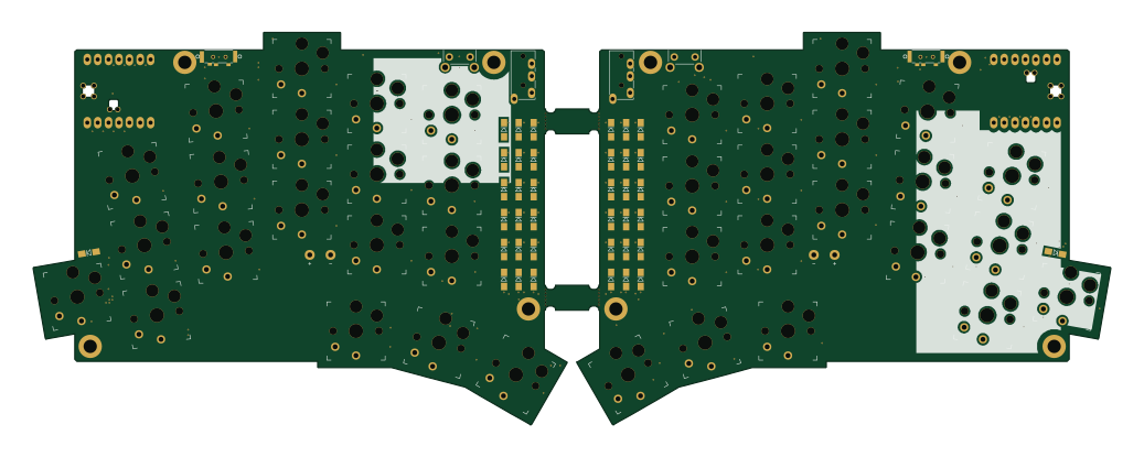
TOTEM
GEIGEIGEIST
258.8 × 94.4 mm85 parts2LCERN-OHL-P-2.02.0k Nordic nRF
Pixl.js
solosky
40 × 23 mm45 parts4LGPL-2.01.4k Nordic nRF
Board hl15-latest
dennisss
61 × 37 mm14 parts2LApache-2.0381 Nordic nRF
Management
101 × 31.5 mm50 parts2LApache-2.0381 Nordic nRF
Board
363 × 128 mm420 parts4LApache-2.0381 Nordic nRF
Mikoto
zhiayang
18 × 33.3 mm53 parts4LApache-2.0355