GPIO Indicator - educational unbuilt DRAFT

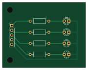
About the GPIO Indicator - educational unbuilt DRAFT PCB
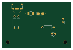
GPIO Indicator - educational unbuilt DRAFT is an open source PCB design by devkyber, published on GitHub. It is a 2-layer board measuring 45 × 35 mm, with 9 components from 3 distinct parts.
By type, the board carries 4 diodes, 4 resistors and 1 connector.
From the project
AI-assisted PCB engineering for native KiCad: source evidence, scoped changes, checked previews, human review, and reproducible release packages.
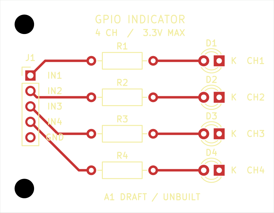
An unbuilt educational DRAFT for trying PCB Copilot on a complete, small KiCad design. Four independent 0 to 3.3 V inputs drive four red LEDs through 1.1 kOhm resistors. The 45 x 35 mm board has two copper layers, through-hole components, two mounting holes, project-local libraries and all three package models.
Open gpio-indicator.kicad_pro in KiCad 10, or inspect the schematic PDF, schematic image, assembly drawing, front copper and mirrored underside. The GLB model is a native CAD visualization; it does not establish actual component fit.
GPIO Indicator - educational unbuilt DRAFT bill of materials (BOM)
9 components, 3 distinct parts — part numbers from the project's BOM.
| Qty | Part | Footprint | Refs |
|---|---|---|---|
| 1 | 61300511121 Wuerth Elektronik | PinHeader_1x05_P2.54mm_Vertical | J1 |
| 4 | WP710A10ID Kingbright | LED_D3.0mm | D1, D2, D3, D4 |
| 4 | MFR-25FBF52-1K1 1.1 kOhm 1% Yageo | R_Axial_DIN0207_L6.3mm_D2.5mm_P10.16mm_Horizontal | R1, R2, R3, R4 |
GPIO Indicator - educational unbuilt DRAFT design files
The KiCad project lives in the devkyber/PCB repository on GitHub; these links point at the commit this page was built from.
GPIO Indicator - educational unbuilt DRAFT: common questions
How big is the GPIO Indicator - educational unbuilt DRAFT PCB?
The GPIO Indicator - educational unbuilt DRAFT measures 45 × 35 mm, has 2 copper layers and is 1.6 mm thick.
How many components are on the GPIO Indicator - educational unbuilt DRAFT?
9 components, from 3 distinct parts, with part numbers taken from the project's own BOM. The full bill of materials is listed on this page.
Where can I download the GPIO Indicator - educational unbuilt DRAFT design files?
From the devkyber/PCB repository on GitHub, which has the KiCad layout, the schematic and the BOM; the links under Design files point to each one.
Can I use the GPIO Indicator - educational unbuilt DRAFT design in my own project?
The repository has no license, so all rights stay with devkyber. Use it as a reference, and ask the author before reusing the design.