
Rover power distribution board

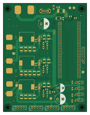
About the Rover power distribution board
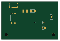
Rover power distribution board is an open source RP2040/RP2350 PCB design by devkyber, published on GitHub. It is a 2-layer board measuring 77.5 × 100 mm, with 73 components from 33 distinct parts.
Its main chip is the Pico 2, from the RP2040/RP2350 family. Other key parts include the INA226AIDGSR and LMR51450SDRRR. By type, the board carries 32 capacitors, 21 resistors, 9 connectors, 4 ICs, 3 inductors and 1 switch.
From the project
AI-assisted PCB engineering for native KiCad: source evidence, scoped changes, checked previews, human review, and reproducible release packages.
The owner closed Rover work on 2026-10-07. This is the sole retained Rover project. Cleanup preserved its native CAD and current manufacturing-preview files byte-for-byte. Earlier development checks below retain their dated scope; closing development does not create a fabrication sign-off.
Open rover-pdb.kicadpro in KiCad. The saved seven-sheet schematic and PCB are the current owner-editable design. PCB P5 / circuit A10 with owner edits and L3 stock substitution, 2026-10-05, retains the owner's 77.5 × 100 mm** outline, two copper layers / 1 oz, four M3 holes, surface wire pads and the saved…
Main components on the Rover power distribution board
Rover power distribution board bill of materials (BOM)
73 components, 33 distinct parts — part numbers from the project's BOM.
| Qty | Part | Footprint | Refs |
|---|---|---|---|
| 1 | INA226AIDGSR | MSOP-10_3x3mm_P0.5mm | U1 |
| 3 | LMR51450SDRRR | LMR51450_DRR_WSON12_3x3 | U2, U3, U4 |
| 1 | B4B-EH-A(LF)(SN) U2D2 DATA IN | JST_EH_B4B-EH-A_1x04_P2.50mm_Vertical | J1 |
| 1 | TSW-103-07-G-S LIFT A | PinHeader_1x03_P2.54mm_Vertical | J2 |
| 1 | TSW-103-07-G-S LIFT B | PinHeader_1x03_P2.54mm_Vertical | J3 |
| 1 | TSW-103-07-G-S CAMERA PAN | PinHeader_1x03_P2.54mm_Vertical | J4 |
| 1 | B4B-EH-A(LF)(SN) LEFT WHEELS | JST_EH_B4B-EH-A_1x04_P2.50mm_Vertical | J5 |
| 1 | B4B-EH-A(LF)(SN) RIGHT WHEELS | JST_EH_B4B-EH-A_1x04_P2.50mm_Vertical | J6 |
| 1 | B4B-EH-A(LF)(SN) HAMMER | JST_EH_B4B-EH-A_1x04_P2.50mm_Vertical | J7 |
| 1 | TSW-103-07-G-S SERVO AUX | PinHeader_1x03_P2.54mm_Vertical | J8 |
| 1 | 2.54-1x6P直针 EXP / DNP | PinHeader_1x06_P2.54mm_Vertical | J9 |
| 1 | CSS2H-2512K-2L00F 2mR / 5W / 1% | CSS2H_2512_6.35x3.05 | RS1 |
| 1 | Pico 2 Pico 2 / 2x20 sockets | Pico2_Sockets_LXWCONN_254PM_1x20 | SKT1 |
| 1 | OS102011MA1QN1 MOTOR ENABLE | SW_Slide_SPDT_Angled_CK_OS102011MA1Q | SW1 |
| 1 | KT-0805G GREEN | KT0805G_0805_A1_K2 | D2 |
| 1 | SRP1265A-6R8M 6u8 / SRP1265A | SRP1265A_LeadFrame_13.5x12.5_P11.1 | L1 |
| 1 | SRP1265A-4R7M 4u7 / SRP1265A | SRP1265A_LeadFrame_13.5x12.5_P11.1 | L2 |
| 1 | APS1365M3R3DW 3u3 / APS1365DW | APS1365DW_13.8x12.6_P11.5 | L3 |
| 2 | EEU-FR1H221B 220u / 50V | CP_Radial_D10.0mm_P5.00mm | C1, C5 |
| 1 | EEU-FR1C471B 470u / 16V | CP_Radial_D8.0mm_P5.00mm | C2 |
Show 13 more
| Qty | Part | Footprint | Refs |
|---|---|---|---|
| 7 | CL21B104KBCNNNC 100n / 50V | C_0805_2012Metric | C3, C30, C31, C32, C33, C34, C35 |
| 10 | GRM32ER71H106KA12L 10u / 50V | C_1210_3225Metric | C10, C11, C12, C13, C14, C15, C16, C17 +2 |
| 9 | CL32B226KAJNNNE 22u / 25V | C_1210_3225Metric | C20, C21, C22, C23, C24, C25, C26, C27 +1 |
| 3 | CL10C330JB8NNNC 33p / 50V | C_0603_1608Metric | C39, C40, C41 |
| 2 | RC0805FR-074K7L 4k7 / 1% | R_0805_2012Metric | R1, R2 |
| 4 | RC0805FR-0710KL 10k | R_0805_2012Metric | R3, R4, R5, R6 |
| 7 | RC0805FR-07100KL 100k / 1% | R_0805_2012Metric | R10, R11, R12, R13, R14, R15, R19 |
| 1 | 0805W8F1912T5E 19.1k / 1% | R_0805_2012Metric | R16 |
| 1 | 0805W8F7151T5E 7.15k / 1% | R_0805_2012Metric | R17 |
| 1 | 0805W8F3741T5E 3.74k / 1% | R_0805_2012Metric | R18 |
| 1 | RC1206FR-073K9L 3k9 / 0.25W | R_1206_3216Metric | R20 |
| 3 | 0805W8F1001T5E 1k / 1% | R_0805_2012Metric | R21, R22, R23 |
| 1 | 0805W8F2202T5E 22k / 1% | R_0805_2012Metric | R24 |
Rover power distribution board design files
The KiCad project lives in the devkyber/PCB repository on GitHub; these links point at the commit this page was built from.
Rover power distribution board: common questions
What microcontroller does the Rover power distribution board use?
The Rover power distribution board is built around the Pico 2, from the RP2040/RP2350 family.
How big is the Rover power distribution board?
The Rover power distribution board measures 77.5 × 100 mm, has 2 copper layers and is 1.6 mm thick.
How many components are on the Rover power distribution board?
73 components, from 33 distinct parts, with part numbers taken from the project's own BOM. The full bill of materials is listed on this page.
Where can I download the Rover power distribution board design files?
From the devkyber/PCB repository on GitHub, which has the KiCad layout, the schematic and the BOM; the links under Design files point to each one.
Can I use the Rover power distribution board design in my own project?
The repository has no license, so all rights stay with devkyber. Use it as a reference, and ask the author before reusing the design.
Can I test firmware for the Rover power distribution board without the hardware?
Yes. HardLabs builds a simulation of the board from its netlist and BOM, so you can run and debug RP2040/RP2350 firmware against it before you order a PCB.
More boards in PCB
Similar boards
 RP2040/RP2350
OSO-BOOK-C1
joeycastillo
85 × 115 mm29 parts2LCC-BY-SA-4.08.1k RP2040/RP2350
Corne cherry
foostan
277.2 × 107.5 mm164 parts2LCC-BY-4.07.7k RP2040/RP2350
Corne chocolate
277.2 × 107.5 mm164 parts2LCC-BY-4.07.7k RP2040/RP2350
Jitx design
gusmanb
55.5 × 65 mm26 parts4LGPL-3.05.0k RP2040/RP2350
LogicAnalyzer
57 × 55.2 mm6 parts2LGPL-3.05.0k RP2040/RP2350
Main
google
98 × 71 mm102 parts2LApache-2.02.9k