
LoadShed

About the LoadShed PCB
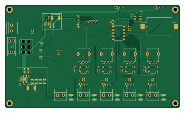
LoadShed is an open source AVR/Arduino PCB design by DJM0, published on GitHub under the MIT license. It is a 2-layer board measuring 151.2 × 89.3 mm, with 90 components from 39 distinct parts.
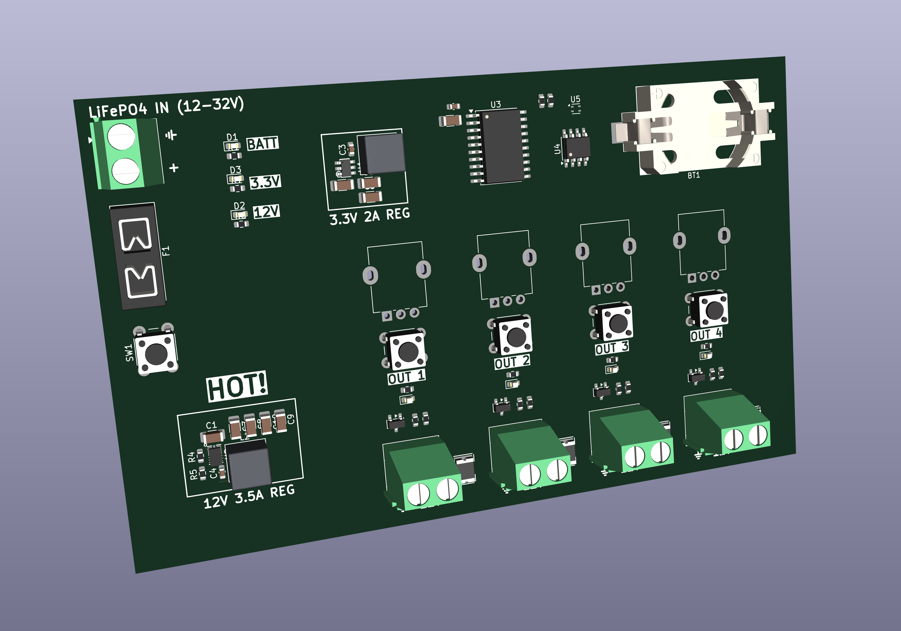
Its main chip is the ATTINY3216-S, from the AVR/Arduino family. Other key parts include the AP63203WU-7, DS3231MZ, SHT4X and AP64502QSP-13. By type, the board carries 24 resistors, 18 capacitors, 14 connectors, 7 diodes, 6 fuses and 5 ICs.
It belongs with the power & battery, iot & wireless and displays & leds designs in this gallery.
From the project
Off-grid 4-channel PWM load controller with regulated 12 V output from any 12–32 V battery. Sunrise/sunset + RTC scheduling, LiFePO₄ battery protection, dimming pots and an OLED. ATtiny3216 firmware + KiCad hardware. No WiFi, no cloud, no app.
KiCad 9 project for the LoadShed PCB. Licensed under CERN-OHL-P v2.
Several parts (regulators, inductors, polyfuses, battery holder, buttons…) were pulled from JLCPCB/LCSC using the kicad-jlcimport plugin, which converts EasyEDA CAD data into a project-local JLCImport library. Because that converted data comes from EasyEDA/LCSC, its redistribution licence is unclear, so the JLCImport symbol/footprint/3D-model libraries are not included in this repo.
Main components on the LoadShed
LoadShed bill of materials (BOM)
90 components, 39 distinct parts — part numbers from the project's BOM.
| Qty | Part | Footprint | Refs |
|---|---|---|---|
| 1 | AP63203WU-7 Diodes Incorporated | AP63203WU-7 | U1 |
| 1 | ATTINY3216-S ATtiny3216-S | SOIC-20W_7.5x12.8mm_P1.27mm | U3 |
| 1 | DS3231MZ | SOIC-8_3.9x4.9mm_P1.27mm | U4 |
| 1 | SHT4X SHT4x | Sensirion_DFN-4_1.5x1.5mm_P0.8mm_SHT4x_NoCentralPad | U5 |
| 1 | AP64502QSP-13 Diodes Incorporated | AP64502QSP-13 | U6 |
| 4 | AO3400A | SOT-23 | Q1, Q2, Q3, Q4 |
| 1 | BATT | TerminalBlock_Phoenix_MKDS-1,5-2-5.08_1x02_P5.08mm_Horizontal | J1 |
| 1 | OUT1 | TerminalBlock_Phoenix_MKDS-1,5-2-5.08_1x02_P5.08mm_Horizontal | J2 |
| 1 | OUT2 | TerminalBlock_Phoenix_MKDS-1,5-2-5.08_1x02_P5.08mm_Horizontal | J3 |
| 1 | OUT3 | TerminalBlock_Phoenix_MKDS-1,5-2-5.08_1x02_P5.08mm_Horizontal | J4 |
| 2 | OUT4 | TerminalBlock_Phoenix_MKDS-1,5-2-5.08_1x02_P5.08mm_Horizontal | J5, J7 |
| 1 | OLED | PinHeader_1x04_P2.54mm_Vertical | J6 |
| 1 | UPDI | PinSocket_1x03_P2.54mm_Vertical | J8 |
| 1 | PB3 | PinSocket_1x03_P2.54mm_Vertical | J9 |
| 4 | Conn_01x03_Socket | PinHeader_1x02_P2.54mm_Vertical | J10, J11, J12, J13 |
| 1 | OLED2 | PinHeader_1x04_P2.54mm_Vertical | J14 |
| 1 | BS-06-B4AA002 MYOUNG | BS-06-B4AA002 | BT2 |
| 1 | 5A | Fuseholder_Blade_Mini_Keystone_3568 | F1 |
| 5 | C1512049 Polyfuse | 1812L300_24SLER | F2, F3, F4, F5, F6 |
| 4 | R_Potentiometer | Potentiometer_Alpha_RD901F-40-00D_Single_Vertical | RV1, RV2, RV3, RV4 |
Show 19 more
| Qty | Part | Footprint | Refs |
|---|---|---|---|
| 1 | POWER SW | T8013_ToggleSwitch_SPDT_1 | SW1 |
| 4 | SW_Push | SW_PUSH_6mm | SW3, SW4, SW5, SW6 |
| 7 | LED | LED_0603_1608Metric | D1, D2, D3, D4, D5, D6, D7 |
| 1 | C167294 4.7µH | 0630CDMCCDS-4R7MC | L1 |
| 1 | C167295 6.8µH | 0630CDMCCDS-6R8MC | L3 |
| 7 | 100NF 100nF | C_0603_1608Metric | C1, C3, C4, C7, C11, C13, C14 |
| 4 | 10UF 10uF | C_1206_3216Metric | C2, C12, C15, C21 |
| 2 | 22UF 22uF | C_1206_3216Metric | C5, C6 |
| 4 | 47UF 47uF | C_1210_3225Metric | C16, C17, C18, C19 |
| 1 | 10NF 10nF | C_0603_1608Metric | C20 |
| 2 | 6K8 | R_0603_1608Metric | R1, R6 |
| 2 | 4K7 | R_0603_1608Metric | R2, R3 |
| 6 | 100K | R_0603_1608Metric | R4, R8, R11, R14, R17, R20 |
| 2 | 27K | R_0603_1608Metric | R5, R21 |
| 5 | 1K | R_0603_1608Metric | R7, R10, R13, R16, R19 |
| 4 | 100R | R_0603_1608Metric | R9, R12, R15, R18 |
| 1 | 140K | R_0603_1608Metric | R22 |
| 1 | 10K | R_0603_1608Metric | R23 |
| 1 | 200K | R_0603_1608Metric | R24 |
LoadShed design files
The KiCad project lives in the DJM0/LoadShed repository on GitHub; these links point at the commit this page was built from.
LoadShed: common questions
What microcontroller does the LoadShed use?
The LoadShed is built around the ATTINY3216-S, from the AVR/Arduino family.
How big is the LoadShed PCB?
The LoadShed measures 151.2 × 89.3 mm, has 2 copper layers and is 2 mm thick.
How many components are on the LoadShed?
90 components, from 39 distinct parts, with part numbers taken from the project's own BOM. The full bill of materials is listed on this page.
Where can I download the LoadShed design files?
From the DJM0/LoadShed repository on GitHub, which has the KiCad layout, the schematic and the BOM; the links under Design files point to each one.
Can I use the LoadShed design in my own project?
Yes, under the terms of its MIT license, which DJM0 chose for the repository.
Can I test firmware for the LoadShed without the hardware?
Yes. HardLabs builds a simulation of the board from its netlist and BOM, so you can run and debug AVR/Arduino firmware against it before you order a PCB.
Similar boards
 AVR/Arduino
Redox keyboard
mattdibi
162.2 × 126.5 mm77 parts2LMIT2.0k AVR/Arduino
ModuleV450
stuartpittaway
30 × 61.4 mm39 parts2LCC-BY-NC-4.01.1k AVR/Arduino
V4
30 × 50 mm38 parts2LCC-BY-NC-4.01.1k AVR/Arduino
Discipline
coseyfannitutti
304.9 × 122.8 mm170 parts2LCC-BY-NC-4.01.0k AVR/Arduino
Megadesk
gcormier
41.7 × 32.2 mm23 parts2LGPL-3.0818 AVR/Arduino
Easyduino Atmega
Hanqaqa
68.8 × 53.6 mm35 parts4LCERN-OHL-P-2.0746