
Expander cv input


About the Expander cv input PCB
Expander cv input is an open source PCB design by doctea, published on GitHub. It is a 2-layer board measuring 29.9 × 128.5 mm, with 14 components from 5 distinct parts.
It belongs with the audio designs in this gallery.
From the project
IMPORTANT: DO NOT USE THESE FOR ANYTHING YET, THEY ARE VERY MUCH PROTOTYPES AND HAVE SOME PROBLEMS!!!!
IMPORTANT: DO NOT USE THESE FOR ANYTHING YET, THEY ARE VERY MUCH PROTOTYPES AND HAVE SOME PROBLEMS!!!!
Files for PCB modules for use by usbmidiclocker project.
- IMPROVE: reduce size of jack holes to make a snugger fit with less wobble? - IMPROVE: Some nice panel graphics!
- DONE: FIX: Replace the voltage regulator with one that will actually be able to deliver enough amps to power the screen and Teensy facepalm - ~~Can work around this for the moment by connecting directly to 5v Eurorack power with eg Dupont cables~~ - FIX: Fix/bridge/remove power diode that prevents power from USB going…
Expander cv input bill of materials (BOM)
14 components, 5 distinct parts — part numbers from the project's BOM.
| Qty | Part | Footprint | Refs |
|---|---|---|---|
| 2 | ADS1015 digital side | PinSocket_1x05_P2.54mm_Vertical | ADS1015_1_DIG1, ADS1015_2_DIG1 |
| 2 | ADS1015 analog side | PinSocket_1x05_P2.54mm_Vertical | ASD1015_1_ANA1, ASD1015_2_ANA1 |
| 2 | 8 pin header | PinHeader_2x04_P2.54mm_Vertical | CV_INPUT_I2C_EXPANDER1, CV_INPUT_I2C_THRU1 |
| 6 | AUDIOJACK2_SWITCHT AudioJack2_SwitchT | Jack_3.5mm_QingPu_WQP-PJ398SM_Vertical_CircularHoles | JACK1, JACK2, JACK3, JACK4, JACK5, JACK6 |
| 2 | 100N 100n | C_Disc_D5.0mm_W2.5mm_P5.00mm | C1, C2 |
Expander cv input design files
The KiCad project lives in the doctea/usb_midi_clocker_hardware repository on GitHub; these links point at the commit this page was built from.
Expander cv input: common questions
How big is the Expander cv input PCB?
The Expander cv input measures 29.9 × 128.5 mm, has 2 copper layers and is 1.6 mm thick.
How many components are on the Expander cv input?
14 components, from 5 distinct parts, with part numbers taken from the project's own BOM. The full bill of materials is listed on this page.
Where can I download the Expander cv input design files?
From the doctea/usb_midi_clocker_hardware repository on GitHub, which has the KiCad layout, the schematic and the BOM; the links under Design files point to each one.
Can I use the Expander cv input design in my own project?
The repository has no license, so all rights stay with doctea. Use it as a reference, and ask the author before reusing the design.
More boards in usb_midi_clocker_hardware

Expander gate output
40.3 × 128.5 mm115 parts2LNo license0
Expander gate output - Copy
40.3 × 128.5 mm114 parts2LNo license0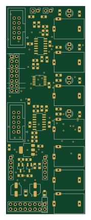
Expander cv output
40.9 × 108 mm76 parts2LNo license0
Expander midi
20 × 128.5 mm44 parts2LNo license0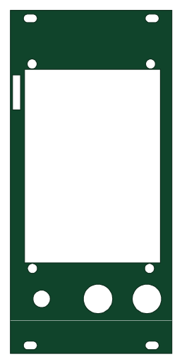 NXP
Usb midi clocker circuits
60.6 × 128.5 mm22 parts2LNo license0 NXP
Expander usb sd
9.8 × 128.5 mm8 parts2LNo license0
Similar boards
KLOR
GEIGEIGEIST
160.2 × 118.3 mm79 parts2LGPL-3.01.2k
USB
shanteacontrols
52 × 12.6 mm6 parts2LApache-2.0956
Pots
390 × 93 mm75 parts2LApache-2.0956
ButtonsLEDs
390 × 37 mm82 parts2LApache-2.0956
PicoGUS Hand386
polpo
29.2 × 75.2 mm43 parts4LGPL-2.0800
Snark barker
schlae
231.1 × 106.7 mm193 parts2LNo license687