
Expander gate output

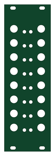
About the Expander gate output PCB
Expander gate output is an open source PCB design by doctea, published on GitHub. It is a 2-layer board measuring 40.3 × 128.5 mm, with 115 components from 20 distinct parts.
Other key parts include the TXS0108EPW and MCP23S17_SS. By type, the board carries 48 diodes, 32 resistors, 10 connectors, 5 capacitors and 3 ICs.
It belongs with the audio designs in this gallery.
From the project
IMPORTANT: DO NOT USE THESE FOR ANYTHING YET, THEY ARE VERY MUCH PROTOTYPES AND HAVE SOME PROBLEMS!!!!
IMPORTANT: DO NOT USE THESE FOR ANYTHING YET, THEY ARE VERY MUCH PROTOTYPES AND HAVE SOME PROBLEMS!!!!
Files for PCB modules for use by usbmidiclocker project.
- IMPROVE: reduce size of jack holes to make a snugger fit with less wobble? - IMPROVE: Some nice panel graphics!
- DONE: FIX: Replace the voltage regulator with one that will actually be able to deliver enough amps to power the screen and Teensy facepalm - ~~Can work around this for the moment by connecting directly to 5v Eurorack power with eg Dupont cables~~ - FIX: Fix/bridge/remove power diode that prevents power from USB going…
Main components on the Expander gate output
Expander gate output bill of materials (BOM)
115 components, 20 distinct parts — part numbers from the project's BOM.
| Qty | Part | Footprint | Refs |
|---|---|---|---|
| 2 | TXS0108EPW | TSSOP-20_4.4x6.5mm_P0.65mm | U1, U2 |
| 1 | MCP23S17_SS | SSOP-28_5.3x10.2mm_P0.65mm | U3 |
| 1 | Output_A_Connector_Backboard | PinSocket_1x10_P2.54mm_Vertical | J1 |
| 1 | Output_B_Connector_Backboard | PinSocket_1x10_P2.54mm_Vertical | J2 |
| 1 | Output_A_Connector_Frontboard | PinHeader_1x10_P2.54mm_Vertical | J3 |
| 1 | Output_B_Connector_Frontboard | PinHeader_1x10_P2.54mm_Vertical | J4 |
| 1 | Eurorack power | IDC-Header_2x08_P2.54mm_Vertical | J5 |
| 1 | CS_SELECT | PinHeader_1x03_P2.54mm_Vertical | J6 |
| 1 | 5V selector | PinHeader_1x03_P2.54mm_Vertical | J7 |
| 1 | ADDR0 | PinHeader_1x03_P2.54mm_Vertical | J16 |
| 1 | ADDR1 | PinHeader_1x03_P2.54mm_Vertical | J17 |
| 1 | ADDR2 | PinHeader_1x03_P2.54mm_Vertical | J18 |
| 1 | 16 pin header | PinHeader_2x08_P2.54mm_Vertical | GATE_SPI_OUTPUT_EXPANDER1 |
| 2 | ~ | Thonkiconn Renumbered | JACK1, JACK14 |
| 14 | fuzzySI_thonkiconn | Thonkiconn Renumbered | JACK2, JACK3, JACK4, JACK5, JACK6, JACK7, JACK8, JACK9 +6 |
| 32 | BAT43 | D_SOD-123 | D1, D2, D3, D4, D5, D6, D7, D8 +24 |
| 16 | LED | LED_D3.0mm | D17, D18, D19, D20, D21, D22, D23, D24 +8 |
| 5 | C_Small | C_0805_2012Metric | C1, C2, C5, C6, C7 |
| 16 | 47K | R_0805_2012Metric | R1, R3, R5, R7, R9, R11, R13, R15 +8 |
| 16 | 1K | R_0805_2012Metric | R2, R4, R6, R8, R10, R12, R14, R16 +8 |
Expander gate output design files
The KiCad project lives in the doctea/usb_midi_clocker_hardware repository on GitHub; these links point at the commit this page was built from.
Expander gate output: common questions
How big is the Expander gate output PCB?
The Expander gate output measures 40.3 × 128.5 mm, has 2 copper layers and is 1.6 mm thick.
How many components are on the Expander gate output?
115 components, from 20 distinct parts, with part numbers taken from the project's own BOM. The full bill of materials is listed on this page.
Where can I download the Expander gate output design files?
From the doctea/usb_midi_clocker_hardware repository on GitHub, which has the KiCad layout, the schematic and the BOM; the links under Design files point to each one.
Can I use the Expander gate output design in my own project?
The repository has no license, so all rights stay with doctea. Use it as a reference, and ask the author before reusing the design.
More boards in usb_midi_clocker_hardware
Expander gate output - Copy
40.3 × 128.5 mm114 parts2LNo license0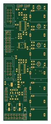
Expander cv output
40.9 × 108 mm76 parts2LNo license0
Expander midi
20 × 128.5 mm44 parts2LNo license0 NXP
Usb midi clocker circuits
60.6 × 128.5 mm22 parts2LNo license0
Expander cv input
29.9 × 128.5 mm14 parts2LNo license0 NXP
Expander usb sd
9.8 × 128.5 mm8 parts2LNo license0
Similar boards
KLOR
GEIGEIGEIST
160.2 × 118.3 mm79 parts2LGPL-3.01.2k
USB
shanteacontrols
52 × 12.6 mm6 parts2LApache-2.0956
Pots
390 × 93 mm75 parts2LApache-2.0956
ButtonsLEDs
390 × 37 mm82 parts2LApache-2.0956
PicoGUS Hand386
polpo
29.2 × 75.2 mm43 parts4LGPL-2.0800
Snark barker
schlae
231.1 × 106.7 mm193 parts2LNo license687