
Remote-Antenna-Switch

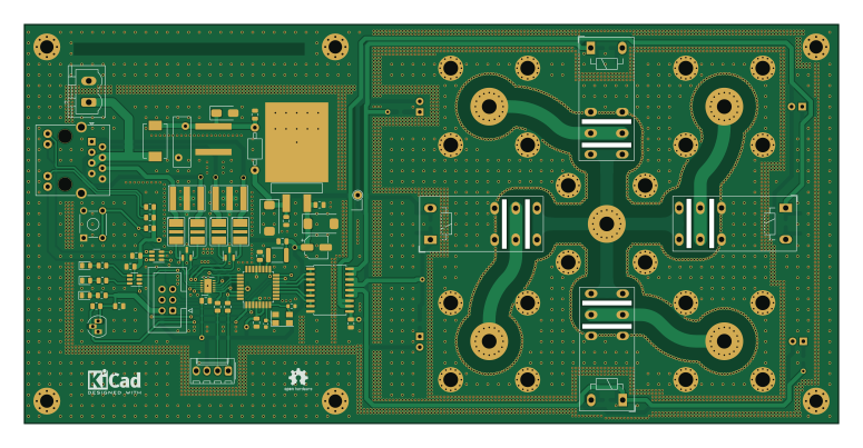
About the Remote-Antenna-Switch PCB
Remote-Antenna-Switch is an open source AVR/Arduino PCB design by EI9SP, published on GitHub. It is a 2-layer board measuring 193.6 × 95 mm, with 82 components from 38 distinct parts.
Its main chip is the ATMEGA328P-AU-atmel, from the AVR/Arduino family. Other key parts include the DS18B20, L7805, ULN2803A, SN74LVC2G34 and LTC2861. By type, the board carries 21 capacitors, 13 resistors, 11 diodes, 9 connectors, 7 ICs and 4 relays.
It belongs with the rf & radio and displays & leds designs in this gallery.
From the project
Four to one Remote Antenna Switch, Full duplex RS485
Main components on the Remote-Antenna-Switch
Remote-Antenna-Switch bill of materials (BOM)
82 components, 38 distinct parts.
| Qty | Part | Footprint | Refs |
|---|---|---|---|
| 1 | DS18B20 | TO-92_HandSolder | U1 |
| 1 | ATMEGA328P-AU-atmel | TQFP-32_7x7mm_P0.8mm | U2 |
| 1 | L7805 | d2-pak_termal | U3 |
| 1 | ULN2803A | SOIC-18W_7.5x11.6mm_P1.27mm | U4 |
| 2 | SN74LVC2G34 | SOT-23-6 | U5, U6 |
| 1 | LTC2861 | DFN-12-1EP_3x4mm_P0.5mm_EP1.7x3.3mm | U7 |
| 1 | 18Mhz | Crystal_SMD_5032-4Pin_5.0x3.2mm | Y1 |
| 1 | AVR-ISP-6-atmel | IDC-Header_2x03_P2.54mm_Vertical | CON1 |
| 1 | 8P8C_LED_Shielded | RJ45_BEL_SS74301-00x_Vertical | J1 |
| 5 | Conn_Coaxial | SO-239 | J2, J3, J4, J5, J6 |
| 1 | Conn_01x04_Pin | Molex_KK-254_AE-6410-04A_1x04_P2.54mm_Vertical | J8 |
| 1 | Conn_01x02_Pin | PhoenixContact_MSTBVA_2,5_2-G-5,08_1x02_P5.08mm_Vertical | J9 |
| 1 | Polyfuse_Small | Fuse_Bourns_MF-SM_7.98x5.44mm | F1 |
| 1 | 2031-23T-SM-RPLF | GDT-2027-XX-SM | GDT1 |
| 2 | 2038-15-SM-RPLF | GDT_2038-xx-SM | GDT2, GDT3 |
| 4 | RT42xxxx | Relay_DPDT_Schrack-RT2-FormC_RM5mm | K1, K2, K3, K4 |
| 1 | Varistor | RV_Disc_D12mm_W4.2mm_P7.5mm | RV1 |
| 1 | SW_Push | SW_TH_Tactile_Omron_B3F-10xx | SW1 |
| 4 | TBU_HSP | TBU-CA | TBU1, TBU2, TBU3, TBU4 |
| 1 | TestPoint | TestPoint_THTPad_D2.0mm_Drill1.0mm | TP1 |
Show 18 more
| Qty | Part | Footprint | Refs |
|---|---|---|---|
| 1 | TVS_unipolar | D_SMA | TVS1 |
| 2 | TVS_Array-SM712 | SOT-23 | TVS2, TVS3 |
| 3 | LED | LED_0805_2012Metric | D1, D2, D3 |
| 4 | SM4003 | D_MELF | D4, D6, D8, D10 |
| 4 | LED | LED_D3.0mm | D5, D7, D9, D11 |
| 1 | 100uH | L_1812_4532Metric | L1 |
| 1 | L_Core_Ferrite | Custom_inductors-BL01RN1A | L2 |
| 1 | 22pF | C_0603_1608Metric | C1 |
| 12 | 100nF | C_0805_2012Metric | C2, C4, C5, C6, C7, C9, C11, C12 +4 |
| 1 | 22pF | R_0603_1608Metric | C3 |
| 2 | CP1_Small | CP_EIA-7343-31_Kemet-D | C8, C10 |
| 1 | CP1_Small | CP_Elec_5x5.9 | C16 |
| 4 | 10nF | C_0805_2012Metric | C17, C18, C19, C20 |
| 1 | 4.7K | R_0805_2012Metric | R1 |
| 3 | R_Small | R_0805_2012Metric | R2, R3, R5 |
| 1 | 10K | R_0805_2012Metric | R4 |
| 6 | 1K | R_0805_2012Metric | R6, R7, R8, R9, R10, R11 |
| 2 | 100 | R_0805_2012Metric | R12, R13 |
Remote-Antenna-Switch design files
The KiCad project lives in the EI9SP/Remote-Antenna-Switch repository on GitHub; these links point at the commit this page was built from.
Remote-Antenna-Switch: common questions
What microcontroller does the Remote-Antenna-Switch use?
The Remote-Antenna-Switch is built around the ATMEGA328P-AU-atmel, from the AVR/Arduino family.
How big is the Remote-Antenna-Switch PCB?
The Remote-Antenna-Switch measures 193.6 × 95 mm, has 2 copper layers and is 1.6 mm thick.
How many components are on the Remote-Antenna-Switch?
82 components, from 38 distinct parts. The full bill of materials is listed on this page.
Where can I download the Remote-Antenna-Switch design files?
From the EI9SP/Remote-Antenna-Switch repository on GitHub, which has the KiCad layout and the schematic; the links under Design files point to each one.
Can I use the Remote-Antenna-Switch design in my own project?
The repository has no license, so all rights stay with EI9SP. Use it as a reference, and ask the author before reusing the design.
Can I test firmware for the Remote-Antenna-Switch without the hardware?
Yes. HardLabs builds a simulation of the board from its netlist and BOM, so you can run and debug AVR/Arduino firmware against it before you order a PCB.
Similar boards
 AVR/Arduino
Magspoof
samyk
35 × 29 mm11 parts2LNo license4.2k AVR/Arduino
Redox keyboard
mattdibi
162.2 × 126.5 mm77 parts2LMIT2.0k AVR/Arduino
Labrador
espotek-org
36.8 × 34.7 mm75 parts2LNo license1.2k AVR/Arduino
V4
stuartpittaway
30 × 50 mm38 parts2LCC-BY-NC-4.01.1k AVR/Arduino
ModuleV450
30 × 61.4 mm39 parts2LCC-BY-NC-4.01.1k AVR/Arduino
Discipline
coseyfannitutti
304.9 × 122.8 mm170 parts2LCC-BY-NC-4.01.0k